Chapter: Civil : Structural dynamics of earthquake engineering
Generalized coordinates and energy methods
Generalized
coordinates and energy methods in relation to structural dynamics during
earthquakes
Abstract: A
structural system consisting of multiple interconnected mass and
flexibilities is modelled as a simple oscillator and the response is studied.
The governing equations are derived based on the principle of virtual work.
RaleighŌĆÖs method is employed to approximate the fundamental frequency of
continuous system. HamiltonŌĆÖs principle is derived and the general dynamic
equilibrium equations are obtained using LagrangeŌĆÖs equations. A program in
MATHEMATICA is given to obtain the dynamic equilibrium equations once Lagrange
equation is given.
Key words: virtual work, shape function,
generalized mass, Rayleigh method, HamiltonŌĆÖs principle, Lagrange
equation.
Introduction
In the earlier chapters, we
obtained the response due to dynamic loads of structures modelled as a simple
oscillator system. In this chapter, we present the response of a structural
system consisting of multiple interconnected rigid bodies or having distributed
mass or flexibility. It will be seen that this will also be modelled as a
single-degree-of-freedom (SDOF) system. The equations are derived based on
principle of virtual work (virtual displacements).
Principle of virtual work
This principle is very useful in
establishing dynamic equation of equilibrium for multiple interconnected rigid
bodies. This principle was originally developed for equilibrium system but it
can also be applied to dynamic system by the simple recourse to DŌĆÖAlembertŌĆÖs
principle. The principle of virtual displacement may be stated as follows:
For a system that is in
equilibrium, the work done by all the forces during an assumed displacement
(virtual displacement) which is compatible with the system constraints is equal
to zero.
To illustrate the application of virtual work, let us consider
a spring massÐ damper system subjected to external force as shown in Fig. 8.1.
Since the inertial forces have been included among the external forces, the
system is
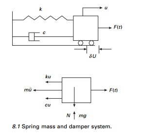
in equilibrium. If a virtual displacement ╬┤u is
assumed to have taken place, the total work done by the forces shown is equal
to zero i.e.

Since ╬┤u is
arbitrary, imaginary not equal to zero, cancelling ╬┤u on both
sides we get

Thus we obtain the differential equation of motion for the
damped oscillator.
Generalized SDOF system: rigid bodies
Most frequently the configuration
of a dynamic system is specified by coordinates indicating the linear or
angular position of elements of the system. Generalized coordinates are
independent coordinates with which we define the deformed shape of the
structure.
The example of the rigid body shown in Fig. 8.2 consists of a
rigid bar with distributed mass m/unit length with rigid mass M
at right end. The rod is supported by springs and dampers. Dynamic excitation
is provided by a transverse load F(x, t) varying in a
triangular fashion as shown in Fig. 8.2. There is also a rotation spring of
stiffness k╬Ė at the
left end. Our purpose is to obtain the differential equation of motion and to
identify the corresponding expressions for parameters of the simple oscillation
representing the system.
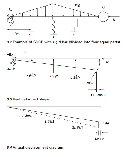
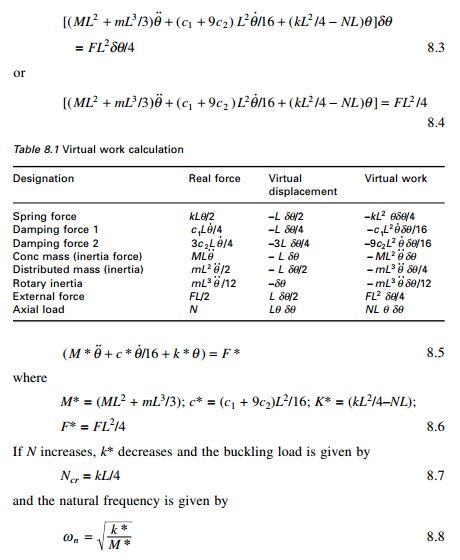
Figures 8.3 and 8.4 represent the
true deformed shape and virtual deformed shape diagram. Since it is a rigid
bar, the internal work is zero. The external virtual work is calculated as
shown in Table 8.1.
Summing up the fourth column of Table 8.1 we get (assuming k╬Ė is zero)
Systems having
distributed stiffness and distributed mass
For systems idealized with
distributed mass and distributed stiffness characteristics, flexural
deformations occur that allow the structure to exhibit an infinite degrees of
freedom. However, a generalized SDOF analysis can be made if it is assumed that
only a single deflection pattern could occur. Hence the motion of the body can
be described by a single variable, or generalized coordinate and only
one degree of freedom exists. Systems idealized in the manner are
referred to as generalized SDOF systems.
Consider a cantilever beam shown in Fig. 8.5. It is assumed
that it has distributed mass and distributed stiffness properties. The vertical
displacement v at any location on the beam is a function of both
position and time, i.e. v(x, t) which can be written as
v(x, t) = Z(t)Žł (x) ŌĆ”ŌĆ”ŌĆ”. ŌĆ”ŌĆ”ŌĆ” 8.9
where Z(t) is the generalized coordinates
representing deflection at the free
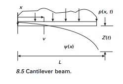
end at any time ŌĆśtŌĆÖ and Žł(x) is the shape
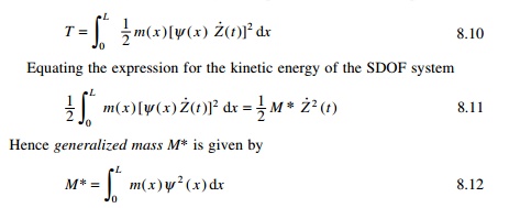
function. The kinetic energy T of the beam shown in Fig. 8.5
vibrating in the pattern indicated by Eq. 8.9 is
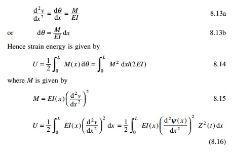
The flexural strain energy U of a prismatic beam may be
determined as the work done by the bending moment M(x) undergoing
angular displacement d╬Ė. This
angular displacement is obtained as
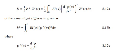
Finally, equating the potential energy Eq. 8.16 for the
continuous system to the potential energy of the equivalent system, we get
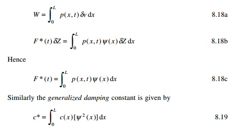
The generalized force F*(t) may be found from
the virtual displacements ╬┤Z(t)
of the generalized coordinate Z(t) upon equating the work
performed by the external forces in the structure to the wok don by the
generalized force in the equivalent SDOF system.
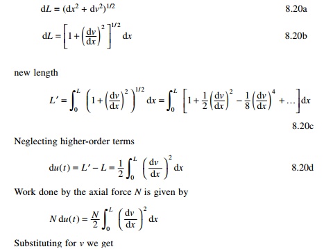
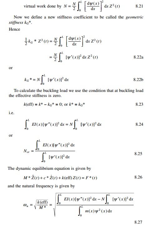
To calculate the potential energy of the axial force N,
which is unchanged during vibration of the beam and consequently is a
conservative force, it is necessary to evaluate the horizontal component of the
motion ╬┤u(t)
at the free end of the beam.
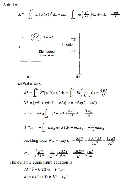
Example 8.1
Determine the dynamic equation of motion, natural frequency
and buckling load of the water tower shown in Fig. 8.6 with distributed mass m,
stiffness EI, concentrated mass at the top = mL. The tower is
subjected to earthquake ground motion of u˙˙g
and an axial compression load at the top. Neglect damping in the system. Assume
that during the motion, the shape of the tower is given by Žł(x) = x2/L2.
8.5
Rayleigh method
The method is based on the
principle of stationary potential energy. Lord Rayleigh in his famous work ŌĆśTheory
of soundŌĆÖ published this work in 1877 states that:
ŌĆśIn a natural mode of vibration
of a conservative system the frequency of vibration is stationary.ŌĆÖ
The Rayleigh method is the basis
for the majority of approximate techniques used in vibration analysis. It may
also be employed to approximate the fundamental frequency of continuous
systems.
From the previous section (assuming concentrated mass = 0),
the displacement at any section X is written as

C is the amplitude of vibration at
the generalized coordinate location. Now, maximum potential energy is
given by
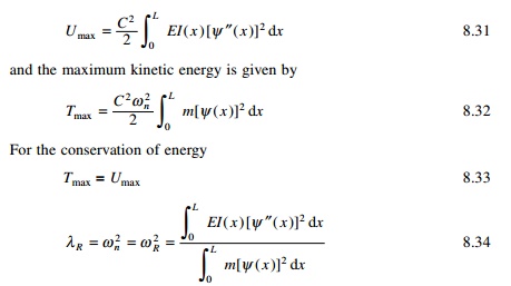
where ŽēR is known
as the Rayleigh frequency.
Obviously, the more closely the assumed shape function Žł(x) approximates the exact
vibration mode, the more accurate will be the estimate of the fundamental
frequency. As a minimum requirement, the assumed shape function should satisfy
the prescribed geometry boundary condition for the problem and also be
differentiable at least to the order appearing in the strain energy expression.
Example 8.2
A uniform cantilever beam shown in Fig. 8.5 of
length L, and having a flexural rigidity EI, cross-sectional area A and mass
density Žü has a concentrated mass M at the free end that is pinned to a linear
spring of stiffness k. Determine Žēn by the Rayleigh method. Assume shape
function as Žł ( x ) = 1 Ōł' cos ŽĆ x /2 L where x is measured from the left
end.
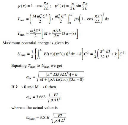
which results in relative error
of 4.18%. If Žł is
assumed as Žł = x2/L2
would result in relative error of of 27.2%. This indicates that the assumed
shape function does not provide an accurate representation of the actual
vibration mode.
Improved Rayleigh
method
The concept of applying inertial
forces as static loads in determining the deformed shape for RayleighŌĆÖs method
may be used in developing an improved scheme for the method. In the application
of the improved RayleighŌĆÖs method, one would start with assumed
deformation curve followed by the calculation of the mass values for kinetic
energy and for potential energy of the system. An approximate value of natural
frequency is calculated by equating maximum kinetic energy with maximum
potential energy. Thus an improved value of natural frequency may be obtained
by loading the structure with inertial loads associated with assumed
deflection. This load results in a new deformed shape which is used for
calculating maximum potential energy.
Example 8.3
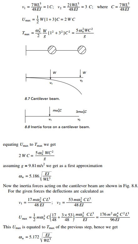
Determine using improved RayleighŌĆÖs
method the natural frequency of the cantilever beam subjected to concentrated
masses (see Fig. 8.7).
For the given loading, as a first step calculate the
deflections under the loads as
HamiltonŌĆÖs principle
The Irish mathematician and physicist Sir William Hamilton
(1805Ð1865) formulated his principle in dynamics in which the governing
equation depends explicitly on the energy of the system.
Consider an ideal system of
interconnected rigid masses whose displacements are uj j
= 1, 2 ├ē n within the interval of time t = t1
to t = t2 as shown in Fig. 8.9. We can plot the
displacement ui as a function of time as shown in Fig. 8.10.
The velocity is obtained by taking time derivative
as
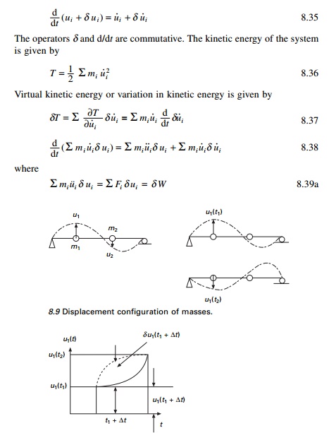
L is termed as
Lagrangian or the kinetic potential when strain energy U alone is
potential.
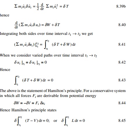
HamiltonŌĆÖs principle states that of all
the possible paths of motion of a system during the interval of time t1 to t2
the actual path will be the one for

LagrangeŌĆÖs equations
The French mathematician Lagrange (1736Ð1813) discovered a
relationship for providing a method of great power and versatility for the
formulation of dynamic equations of equilibrium. Consider a system of connected
rigid bodies.
Example 8.4
Obtain the dynamic equation of
equilibrium using Lagrange equations. m = mass/unit length of the
cylinder, L = length of the cylinder, M = mass of the rectangular
block, r = radius of the cylinder (see Fig. 8.11).
Example 8.5
A simple pendulum of length L
and end mass m pivots about a body of mass M that vibrates in a
horizontal plane as shown in Fig. 8.12. Use LagrangeŌĆÖs equation to
determine the equation of motion. Assume small oscillations.
Example 8.6
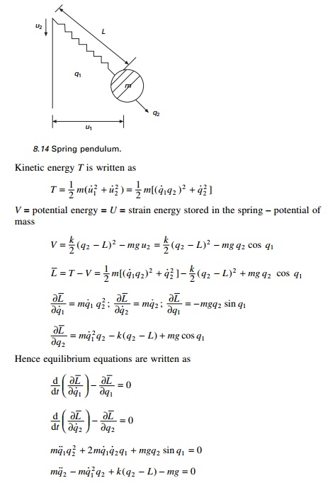
Write Lagrange dynamic equations
of equilibrium for the spring pendulum having a mass ŌĆśmŌĆÖ suspended by an
elastic spring of stiffness ŌĆśkŌĆÖ and free length L. Assume the
pendulum moves without any friction (see Fig. 8.14) and that horizontal and
vertical positions at instant of time are two generalized degrees of freedom.
Solution
u1 = f1 (q1
, q 2 ) = q 2 sin q1
u 2 = f 2 (q1
, q 2 ) = q 2 cos q1
u˙1 = q˙ 2 sin q1
+ q 2 q˙1 cos q1
u˙ 2 = q˙ 2 cos q1
Ōł' q 2 q╦Ö1 sin q1
For small oscillations cos q1 = 1; sin q1
= 0. So
u˙1 = q 2 q˙1 ; u˙
2 = q˙2
Computer-generated Euler-Lagrange equations
using MATHEMATICA
Since the EulerÐLagrange
equations follow in a unique way once a generic functional is given, a computer
may be used to find the derivative. Below we begin with a program which derives
a single equation, and then extend this approach to a system with two degrees of
freedom.
1.SDOF system
Starting with harmonic oscillator (see Fig. 8.15) formulate
its Lagrangian, L and its derivatives.
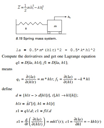
Here h1 is the generalized coordinate and h1t
is the velocity. The equation of equilibrium is obtained as

The following shows the listing of the MATHEMATICA program.
2. Program 8.1: MATHEMATICA program to obtain dynamic
equilibrium equations from Lagrangian for SDOF
ŌĆ£SINGLE DEGREES OF
FREEDOMŌĆØ
ŌĆ£state the lagrangian of the simple
oscillatorŌĆØ la=0.5*m*(h1t)^2-0.5*k*h1^2;
ŌĆ£compute the derivatives and get
one Euler-Lagrange equationsŌĆØ
q1=D[la,h1t];f1=D[la,h1]; d={h1t->D[h1[t],t],h1->h1[t]};
s1=q1/.d;c1=f1/.d;
equation1==Simplify[f1-D[s1,t]]
ŌĆ£SINGLE DEGREES OF
FREEDOMŌĆØ
ŌĆ£state the lagrangian
of the simple
oscillatorŌĆØ
ŌĆ£compute the derivatives and get
one Euler-Lagrange equationsŌĆØ
equation1 == -h1*k
- m*Derivative[2][h1][t]
The program applies to other
systems of a SDOF system provided the Lagrangian is properly specified.
3. Two
degrees of freedom
Consider two bar pendulum shown in Fig. 8.16.
V = Ðm2gL2
cos ╬Ė2 ├É (m1
+ m2)gL1 cos ╬Ė1
T = (m1 + m 2 ) L12
╬Ė╦Ö12 /2 + m l L22╬Ė╦Ö 22 /2 + m 2 L1 L2 ╬Ė╦Ö1╬Ė╦Ö 2 cos (╬Ė 1 Ōł' ╬Ė 2 )
A program in MATHEMATICA for the
above two degrees of freedom is given below.
4. Program 8.2: MATHEMATICAL program to obtain dynamic
equilibrium equations from Lagrangian for two-degrees-of-freedom system
ŌĆ£TWO DEGREES OF
FREEDOMŌĆØ
ŌĆ£state the lagrangian of the non-linear pendulum using (D19.1)
and (D19.2)ŌĆØ
l a = ( m 1 + m 2 ) * L 1 ^ 2 * h 1
t ^ 2 / 2 + m 2 * L 2 ^ 2 * h 2 t ^ 2 / 2+m2*L1*L2*h1t*h2t*Cos[h1-h2]+
m2*g*L2*Cos[h2]+(m1+m2)*g*L1*Cos[h1];
ŌĆ£compute the derivatives and get
two Euler-Lagrange equationsŌĆØ q1=D[la,h1t];q2=D[la,h2t];f1=D[la,h1];f2=D[la,h2];
d={h1t->D[h1[t],t],h2t->D[h2[t],t],h1->h1[t],h2->h2[t]};
s1=q1/.d;c1=f1/.d;s2=q2/.d;c2=f2/.d;
equation1==Simplify[c1-D[s1,t]] equation2==Simplify[c2-D[s2,t]]
Out[19]=
TWO DEGREES OF FREEDOM Out[20]=
state the lagrangian of the
non-linear pendulum using (D19.1) and (D19.2)
Out[22]=
compute the derivatives and get two
Euler-Lagrange equations
Out[26]=
2
equation1 == -(L1 (g m1 Sin[h1[t]]
+ g m2 Sin[h1[t]] + L2 m2 Sin[h1[t] - h2[t]] h2'[t] + L1 (m1 + m2) h1'ŌĆÖ[t] +
L2 m2
Cos[h1[t] - h2[t]]
h2'ŌĆÖ[t]))
Out[27]=
2
equation2 == -(L2 m2 (g Sin[h2[t]]
- L1 Sin[h1[t] - h2[t]] h1'[t] + L1 Cos[h1[t] - h2[t]] h1'ŌĆÖ[t] + L2 h2'ŌĆÖ[t]))
By changing the expression for
the Lagrangian with the help of the editor, one may investigate other systems
of two or three degrees of freedom.
Summary
In many practical situations, NewtonŌĆÖs second law would be
sufficient to obtain the equations of motion for multiple-degrees-of-freedom
systems. But when the system is complex, using the Lagrange equations, one can
write the equations of motion in terms of generalized coordinates. HamiltonŌĆÖs
principle is a general variational principle from which Lagrange equations are
derived. It is also seen that multiply interconnected rigid bodies may be
modeled as a simple oscillator. In the next chapter, we will consider free and
forced vibration of undamped two or three degree of freedom system.
Related Topics