Chapter: 11th 12th std standard Class Physics sciense Higher secondary school College Notes
Generation of sinusoidal waves by a tuned LC circuit
Generation of sinusoidal waves by
a tuned LC circuit
Sinusoidal oscillators consist of
two main sections : a frequency determining device and maintaining device. A
resonant LC network can be used as frequency determining device. The frequency
maintaining device is a transistor amplifier with its power supply. The
amplifier must have sufficient gain to compensate for the attenuation of the
frequency determining section and must introduce required phase shift for
positive feedback.
If a capacitor of capacitance C
and an inductor of inductance L are connected in parallel, then such a circuit
represents an oscillatory circuit.
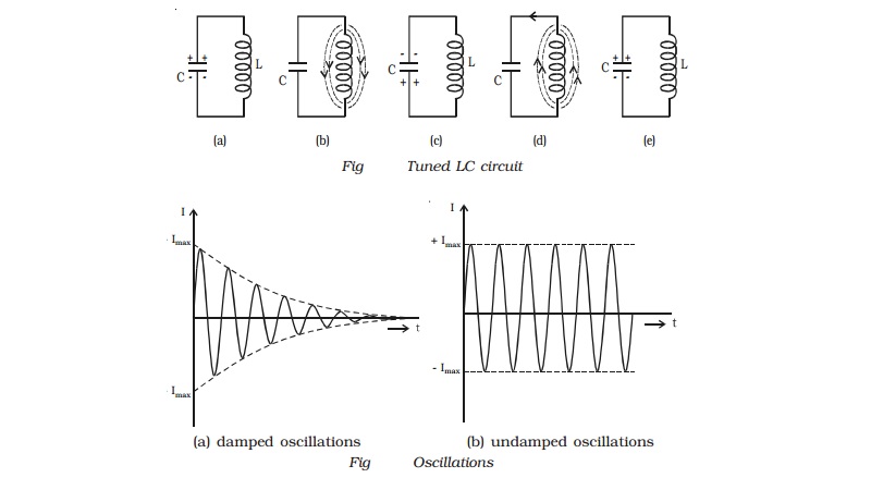
Let us consider a fully charged
capacitor C connected with an inductance L as shown in Fig a. When the charged
capacitor is connected to inductance L, the capacitor will discharge, sending
current through L and induce magnetic field as shown in Fig b. Thus the
electrostatic energy stored in the capacitor has been converted into
electromagnetic energy associated with inductance L.
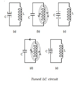
When the capacitor is completely
discharged, the induced magnetic field begins to collapse, sending current in
the same direction. The capacitor C is now charged with opposite polarity (Fig
c). In this case, energy associated with magnetic field is converted into
electrostatic energy. This energy is stored in the capacitor. Once the
capacitor is completely charged, it begins to discharge in the reverse
direction producing again a magnetic field across L in the opposite direction
(Fig d). Again the magnetic field will collapse and will charge the capacitor.
The circuit returns to the original state. (Fig e). This charging and
discharging process results in oscillating current and hence electrical oscillations
are set up in the LC circuit. When a LC circuit is used to store energy, it is
called tank circuit. The frequency of oscillations is given by,
f= 1/ 2π/rt(LC)
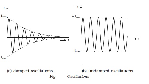
If there are no power losses in
the LC circuit, then the electrical oscillations will continue for indefinite
time. But, in practice, there is some power loss during each cycle of
oscillation, as some resistance is always associated with a given LC circuit.
Hence the amplitude of oscillations decreases gradually and becomes zero, when
all the energy is consumed as losses. Therefore, damped oscillations are
produced in the circuit (Fig a). Imax represents the maximum current
flowing through the circuit.
Related Topics