Chapter: Civil : Structural dynamics of earthquake engineering
Modal response of Earthquake analysis of linear systems
Earthquake analysis of linear systems
Usually the systems are idealized
as lumped-mass systems. In the first part, we will find the structural response
as a function of time when the system is subjected to ground acceleration This
is known as the response history analysis (RHA) procedure. In the second part,
we can compute peak response of a structure during an earthquake directly from
earthquake response or design spectrum without the need for response history
analysis. The values given by response spectrum analysis (RSA) are fairly
accurate.
1 RHA
Let us assume that
earthquake-induced motion u˙˙g ( t ) is
identical to all support points. The equation of motion can be written as
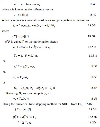
╬ōn is called modal participation
factor, implying that it is a measure of the degree to which the nth
mode participates in the response. ╬ō
is not independent of how the mode is normalized nor a measure of modal
contribution to response quantity.
Modal response
Displacement in physical
coordinates may be obtained as
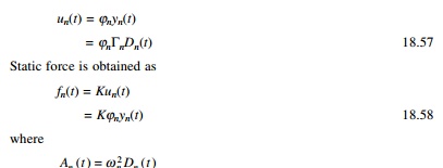
The
equivalent static force is the product of two quantities:
ŌĆó nth mode contribution;
ŌĆó pseudo-acceleration
response of the nth mode SDF system.
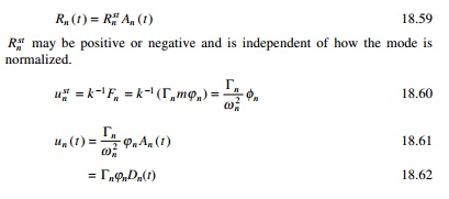
The nth modal contribution
to any response quantity R(t) may be determined by static
analysis of structures subjected to external force fn(t).
If Rnst is the static value
Rnst may be
positive or negative and is independent of how the mode is normalized.
1 Total response
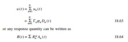
The response contributions of
some of the higher modes may under appropriate circumstances be determined by
simple static analysis instead of dynamic analysis. For short periods Tn
Ōēż 1/33
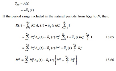
If the period range included is the natural periods from Nd+1
to N, then,
2 Interpretation of modal analysis
At first the dynamic properties
natural frequencies and mode shapes of the structure are computed and the force
distribution vector mi is expanded into modal components. The rest of
the analysis procedure is shown schematically in Table 18.8.
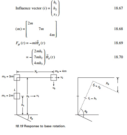
3 Analysis of response to base rotation
The modal analysis procedure is
applicable after slight modification when the excitation is base rotation.
Consider the cantilever frame shown in Fig. 18.19.
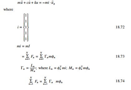
Multi-storey buildings with symmetrical plan
The equation of motion for this
structure is (see Fig. 18.20)
Example18.9
The two storey shear frame shown
in Fig. 18.21 is excited by a horizontal ground motion u˙˙g
( t ). Determine
(a) modal
expansion of effective earthquake forces;
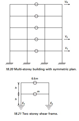
(b) the floor
displacement response of Dn(t);
(c) the
storey shear in terms of An(t);
(d) the first
floor and base overturning moments in terms of An(t).
= D2 ( t )
which is same as [ k ] ŌĆō1( F2
)Žē n22 D2 ( t )
ŌĆō.207
Combining we get
u1(t)
= 0.854 D1(t) + 0.146 D2 (t)
u2(t) = 1.207 D1(t) ŌĆō 0.207 D2
(t)
(c) Storey
shear can be determined as follows (see Fig. 18.23). Substituting this we get
storey shear as
Vbst = 1.4565 m A1
( t ) + 0.0425 m A2 ( t )
V1 (t )
= 0.6035 m A1 (t ) ŌĆō 0.1035 m A2
(t )
(d) Static
analysis of the structure for external floor stress FN gives
static responses M bst , M1st
for the overturning moments Mb, and M1 at
the base and first floor respectively.
Mbst
(
t ) = 2.062 mh A1 ( t ) ŌĆō 0.062 mh A2
( t )
M1(t)
= 0.604 mh A1(t) ŌĆō 0.104 mh A2(t)
Example 18.10
Figure 18.24 shows a two storey
frame with flexural rigidity EI for beams and columns (span of the beam
= 2h). Determine the dynamic response of the structure to horizontal
ground motion u˙˙g (t ) and express
(a) floor displacement and joint rotations in terms of Dn (t); the bending moments in a first storey
column and in the second floor
(b) beam in terms of An(t).
18.12.1 Modal responses
The relative lateral displacement Uin(t)
is written as
Ujn(t)
= ╬ōnŽĢijDn(t)
The storey drift is
Djn(t)
= Ujn(t) ŌĆō UjŌĆō1,n(t)
= ╬ōn(ŽĢjn ŌĆō ŽĢjŌĆō1, n)Dn(t)
The equivalence static force for the nth mode fn(t)
is given by
fn(t)
= FnAn(t)
fjn(t)
= FjnAn(t)
where fjn(t) is lateral force at any jth
floor level.
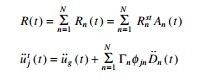
Rn(t)
due to nth mode is given by
Rn
(
t ) = Rnst
An ( t )
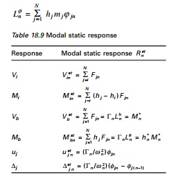
The modal static response Rn(st)
is determined by static analysis of building due to the external force Fn.
The modal static responses are presented in Table 18.9, where
2 Total response
Combining the response
contribution of the entire mode gives the earthquake response of the
multi-storey building
The steps
of analysis are given below:
1. Define
ground acceleration u˙˙g ( t )
numerically at every time step Ōłåt.
2. Define
structural properties:
(a) determine
mass and stiffness matrix,
(b) estimate
modal damping ratio.
3. Determine
natural frequencies (Tn = 2ŽĆ/Žēn) and
natural modes of vibration.
4. Determine
modal components RN of the effective earthquake force
distribution.
5. Compute
the response contribution of nth mode by following steps:
(a) Perform
static analysis of building subjected to Fn forces.
(b) Determine
pseudo-acceleration response An(t) for the nth
mode of SDOF system.
(c) Determine
An(t).
6. Combine modal contributions Rn(t) to determine the total response. As already seen, only lower fewer modes contribute significantly to the response. Hence steps 3, 4 and 5 need to be implemented only for these modes.
Related Topics