Chapter: Civil : Structural dynamics of earthquake engineering
Design examples using IS1893 2002
Design examples using IS1893 2002 Part 1
Example 19.1
Generalize the base width requirement for a wall subjected to an earthquake for given height and weight. Calculate the base width in terms of height in zone V. Assume the wall is rigid (see Fig. 19.3).
Solution
Resisting moment = (Wb/2) > Mo for stability
Mo = EQ ├Ś h/2 E Q = Ah ├Ś W
From IS1893 clause 6.4.2 (assume sa/g = 1)
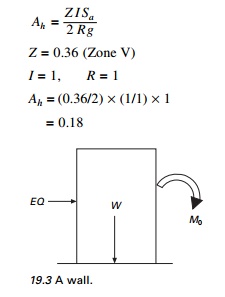
EQ = 0.18 ├Ś W
Mo = 0.18 ├Ś W ├Ś (h/2)
For stability,
Resisting moment > Mo
Wb/2> 0.18 Wh/2
b > 0.18h
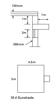
Example 19.2
Check the stability of sunshade of 1 m outer projection. Room size = 5 m ├Ś 4.5 m. Load coming on slab = 2.4 kN/m2. Other dimensions are given in Fig. 19.4. Building located on zone V. Thickness of sunshade = 0.06 m.
Solution
Weight of slab finishes = 5 ├Ś 4.5 ├Ś (0.12 ├Ś 24 + 2.4)
= 118.8 kN
Load per unit length = 118.8/19
= 6.25 kN/m
Earthquake force calculation
W = W of slab + W of wall
According to clause 6.4.5.
Design acceleration spectrum in vertical direction = 2/3 of Ah
According to clause 7.12.2.2. all horizontal projections shall be designed and checked for stability for 5 Ah
EQ = 5 ├Ś (2/3 Ah) ├Ś Wsunshade
Wsunshade = 1 ├Ś 1 ├Ś 0.06 ├Ś 24 = 1.44
Z = 0.36
I = 1
R = 1
Sa/g =1
Ah = 0.18
EQ = (10/3) ├Ś 0.18 ├Ś 1.44
= 0.864 kN
Mo = (Wsunshade + E Q) ├Ś 1/2
= (1.44 + 0.864) ├Ś 1/2
= 1.152 kN/m
To calculate the weight of the wall, if the height of the wall above the lintel i.e., 1 m < 0.866 ├Ś 1.25 m the whole rectangular portion of masonry load between slab and sunshade and slab load to be taken.
Height of wall = 0.866 ├Ś 1.25
Weight of slab = 6.25 kN/m
Weight of wall = 1 ├Ś 0.2 ├Ś 19 kN/m
= 3.8 kN/m
Total load = 10.05 kN/m
MR = (1 ŌĆō Ah 2/3) ├Ś W ├Ś width of wall/2
= (1 ŌĆō 0.12) ├Ś 10.05 ├Ś 0.20/2
= 0.8841 kN/m
MR < Mo
Hence the design is unsafe.
Example 19.3
Determine the design seismic force and design suitable bracing for an overhead water tank shown in Fig. 19.5a supported on steel bracing in Zone V. The weight of the empty water tank is 1000 kN and it can hold water of 2000 kN. The tank is supported by 4 ISMB 400@616 N/m. Assume weight of staging to be 180 kN.
Solution
Damping ratio = 2% since it is a steel structure
1. When tank is empty
W = 1000 + 180/3
= 1060 kN
For first trial, assume Sa/g = 2.5. For Žü = 2%, magnification factor = 1.4, so
Sa/g = 1.4 ├Ś 2.5
= 3.5
Horizontal seismic force: since it is a water tank
importance factor I = 1.5
Response reduction factor R = 4
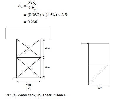
Base shear = 0.236 ├Ś 1060
= 245.4 kN
2.When tank is full
W = 1000 + 2000 + 180/3 = 3060 kN
Ah = 0.236
Base shear = 0.236 ├Ś 3060 = 708.4
Design of bracing (see Fig. 19.5b)
One is subjected to tension and other to compression.
Force in brace = 708.4/cos 45
= 1001.8 kN
Net area required for brace = ╬│mlTdn/(╬▒┬┤fu)
╬│ml = 1.25
fu = 410 MPa
╬▒┬┤ = 0.6 (for 1 or 2 bolts)
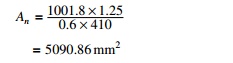
Assume bolt size of 20 mm of high strength friction grip (HSFG). Thickness of angle =12 mm
Area of bolt = 21.5 ├Ś 12 = 258 mm2
Gross area = (5090.86 + 258 ├Ś 2) = 5606 mm2
Choose double angles 2 ├Ś ISA 150 ├Ś 150 ├Ś 10 area = 5806 mm2> 5606 rmin = 46.3 mm
l/rmin = 5656/46.3
= 122.2<350
Hence OK.
(i) Stiffness of the column in each bay can be taken as
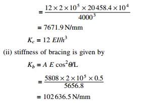
(ii) In each bay there are four columns and two bracings, one on either side. The two other bracings are assumed to buckle under compression therefore the total stiffness of the bay becomes
K1 = 4kc + 2kb = 4 ├Ś 7671.9 + 2 ├Ś 102 636.5 = 235 960.6 kN/m
Since there are two bays, one over the other, the stiffness of the staging k is given by
1/ke = 1/k1 + 1/k1 and so ke = k1/2 = 117 980.3 kN/m
For T = 0.327, Sa/g = 2.5 ├Ś 1.5
The same acceleration as assumed as initially since there is no need for iteration. Provide double angles 2 ├Ś ISA 150 ├Ś 150 ├Ś 10 of area = 5806 mm2 for
bracing.
Example 19.4
Determine the design seismic load by the response spectrum method of IS1893 2002 for a three storey residential building with the following information. The live loads are 4 kN each for all the three storeys. The height is 3 m each. The building is a residential with an ordinary moment resisting concrete frame. It is located in Zone V and the building has the following details centre to centre of the frame is 3 m (in each storey exterior colomns are of same size).
Column sizes c1 = 230 ├Ś 300 mm
c2 = 230 ├Ś 380 mm
c3 = 230 ├Ś 230 mm
Beam sizes B1 = 230 ├Ś 300 mm
Reinforced cement concrete slab = 120 mm thick
Walls = 230 mm thick, fck = 20 MPa; fy = 415 MPa; Zone V = rock, density of concrete = 25 kN/m3.
The elevation and plan of the structure are shown in Fig. 19.6.
Solution
Dynamic analysis should be performed to obtain design seismic force for the following buildings: (a) regular building whose height >40 m in Zones IV and V and those >90 m in height in Zones II and III, (b) irregular buildings: all buildings higher than 12 m in Zones IV and V and 40 m in Zones II and III.
Load calculation
Calculation of dead weight of each floor:
Weight of beam = (2 ├Ś 2 ├Ś 0.23 ├Ś 0.3 ├Ś 25) + (2 ├Ś 3 ├Ś 0.23 ├Ś 0.3 ├Ś 25) = 17.25 kN
Weight of column
for 1st and 2nd storey = (2 ├Ś 3 ├Ś 0.23 ├Ś 0.3 ├Ś 25)
+ (3 ├Ś 3 ├Ś .23 ├Ś 0.38 ├Ś 25)
= 30.015 kN
For 3rd storey = (2 ├Ś 3 ├Ś 0.23 ├Ś 0.23 ├Ś 25)
+ (3 ├Ś 3 ├Ś 0.23 ├Ś 0.3 ├Ś 25)
= 23.46 kN
Weight of slab = (2 ├Ś 2 ├Ś 3 ├Ś 0.12 ├Ś 25) + (2 ├Ś 3 ├Ś 3 ├Ś 0.12 ├Ś 25) = 90 kN
Weight of wall = (2 ├Ś 2 ├Ś 3 ├Ś 0.23 ├Ś 18) + (2 ├Ś 3 ├Ś 3 ├Ś 0.23 ├Ś 18) = 124.20 kN
Calculation of live load, as per IS1893 (I): 2002 Table 8 clauses 7.3.1 and 7.3.2
Live load at 1st floor and 2nd floor level = (2 ├Ś 2 ├Ś 3 ├Ś 4 ├Ś 0.5) + ( 2 ├Ś 3 ├Ś 3 ├Ś 4 ├Ś0.5)
= 60 kN
Lumped weight at each floor:
Floor level 1 = 17.25 + 30.01 + 90 + 124.2 + 60 = 321 kN
Floor level 2 = 17.25 + (30.01/2) + (23.46/2) + 90 + 124.2 + 60 = 318 kN
Roof level = 17.25 + (23.46/2) + 90 + (124.2/2) = 181 kN
Therefore, W1 = 321 kN
W2 = 318 kN
W3 = 181 kN
Lumped mass at each floor:
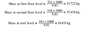
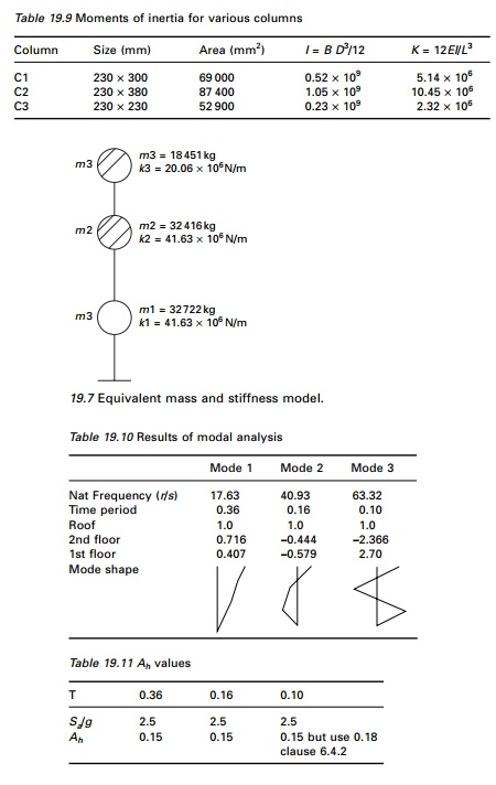
Therefore, m1 = 32 722 kg m2 = 32 416 kg m3 = 18 451 kg
As per IS456: 2000 Clause 6.2.3.1.
Stiffness of columns (K)
E = modulus of elasticity of concrete = 5000 fck = 5000 ├Ś 20
E = 22 360 N/mm2
L = length of column = 3 m
The moments of inertia of various columns are given in Table 19.9. Stiffness of column on first storey = (2 ├Ś 5.14 ├Ś 106)
+ (3 ├Ś 10.45 ├Ś 106) = 41.63 ├Ś 106 N/m
Stiffness of column on second storey = (2 ├Ś 5.14 ├Ś 106)
+ (3 ├Ś 10.45 ├Ś 106) = 41.63 ├Ś 106 N/m
Stiffness of column on third storey = (2 ├Ś 2.32 ├Ś 106) + (3 ├Ś 5.14 ├Ś 106)
= 20.06 ├Ś 106 N/m
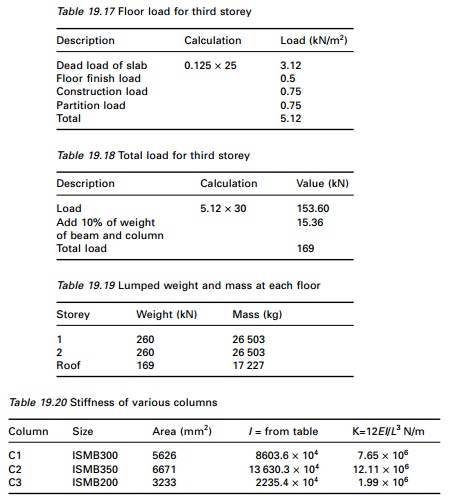
The stick model is shown in Fig. 19.7.
Modal analysis
From modal analysis we get the results shown in Table 19.10.
Design horizontal seismic coefficient
Ah = (z/2) ├Ś (I/R) ├Ś (Sa/g)
Z = 0.36
R = 3
I = 1
Ah values are given in Table 19.11.
As per Clause 6.4.2 for T Ōēż 0.1 s, Ah Ōēż Z/2 = 0.18 whatever the value of
I/R.
Modal mass Mk and modal participation factor Pk (see Table 19.12)
Participation factors and percentage of modal mass have been calculated as shown in Table 19.12.
Design lateral force at each floor and storey shear
Lateral force Qik = AhPkWiŽåik

Lateral force Qik and shear force Vik (see Table 19.13).
Storey shear force due to all mode and lateral force at each storey
Applying the SRSS rule (see Table 19.14)
Example 19.5
Analyse and design a steel moment resisting frame for the building shown in Fig. 19.6. Also determine the design seismic force by the response spectrum method of IS1893: 2002. The live load is 4.0 kN each for all the three stories is 3.0 m each. The building is residential with a special moment resisting frame. It is located in Zone V and the building has the following details.
fck = 20 N/mm2 fy = 250 N/mm2 fy = 415 N/mm2
Zone V Rock soil site
Density of concrete = 25 kN/m3
Live load = 4 kN/m2
Column sizes
C1 = ISMB300@44.2 kg/m
C2 = ISMB350@52.4 kg/m
C3 = ISMB200@25.4 kg/m
Beam size B1 = ISMB200@25.4 kg/m
Solution
(A) Load calculation (see Tables 19.15ŌĆō19.19)
Floor area = (2 ├Ś 2 ├Ś 3) +( 2 ├Ś 3 ├Ś 3 ) = 30 m2
Floor load calculations for the first, second and third storey are shown in Tables 19.15ŌĆō19.18. The lumped weight and mass at each floor are shown in Table 19.19.
(B) Stiffness of columns (see Table 19.20)
E = modulus of elasticity of steel = 2 ├Ś 105 N/mm2
L = length of column = 3 m
Stiffness of column on first and second storey
= (2 ├Ś 7.65 ├Ś 106) + (3 ├Ś 12.11 ├Ś 106)
= 51.63 ├Ś 106 N/m
Stiffness of column on third storey = (2 ├Ś 1.99 ├Ś 106) + (3 ├Ś 7.65 ├Ś 106)
= 26.93 ├Ś 106 N/m
(C)Modal analysis (see Table 19.21)
(D)Design horizontal seismic coefficient
Z = 0.36
I = 1
R = 5
The horizontal seismic coefficients are given in Table 19.22.
(E) Modal mass and participation factor
The calculations are shown in Table 19.23.
Pk1 = 460/344 = 1.34
Pk2 = ŌĆō144/360 = ŌĆō0.4
Pk3 = 268/4173 = 0.06
Wk1 = 1.34 ├Ś 460 = 616
Wk2 = ŌĆō0.4 ├Ś ŌĆō144 = 57.6
Wk3 = 0.06 ├Ś 268 = 16.08
Percentage contribution for 1st mode = 616/689 = 89.4 Percentage contribution for 2nd mode = 57.6/689 = 8.27 Percentage contribution for 3rd mode = 16.08/689 = 2.46
()Design lateral force for each storey (see Table 19.24)
Apply the SRSS rule.
(G)Storey shear due to all modes (see Table 19.25)
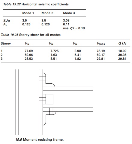
(H) Analysis of frames
The frame is analysed as a plane frame for dead load, live load and lateral load obtained by response spectrum method for various load combinations. Partial safety factor for limit state design of steel structures:
(a) 1.5(DL + LL)
(b) 1.2(DL + LL ┬▒ EL)
(c) 1.5(DL ┬▒ EL)
(d) 0.9(DL ┬▒ 1.5EL)
Moment resisting connection (see Fig. 19.9)
Storey drift (max) = 0.004 ├Ś storey height
Storey drift (actual) = storey shear/stiffness
Storey drift calculations are shown in Table 19.26.
(J) Column thickness
The individual thickness of the column and doubler plates should satisfy the following (as per IS800 draft)
where
t = thickness of doubler plate or column web dp = panel zone between continuity plate
bp = panel zone between column flanges (see Tables 19.27 and 28).
(K) Beam and column limitation
The section selected for beams and columns shall satisfy the following
where
ŌłæMpc = sum of the moments above and below column centrelines ŌłæMpb = sum of the moments in the beam at the intersection of the
beam and column centrelines
In all the elements the ratio is greater than 1.2.
Conclusion: From the above result it is proved that the provided sections are efficient in carrying dead load, live load and earthquake load.
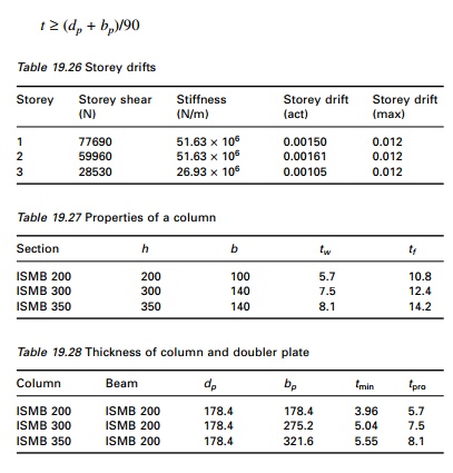
Example 19.6
Find the seismic load on shear building shown in Fig. 19.10 by varying the stiffness of columns and mass of the floors. Table 19.29 gives the comparison.
Example 19.7
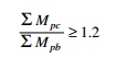
Calculate the shear force at the ground storey columns for the following building (Zone V; rock; concrete column, Fig. 19.11) h = 3 m.
Data given: G + 2, slab; 120 mm thick, walls = 230 mm brick Live load: 4 kN/m2
Column size GF: 230 ├Ś 300, FF = 230 ├Ś 300, SF = 230 ├Ś 230
Beam size: 230 ├Ś 300 (0.1 m thick weathering course may be assumed on the roof)
(Assume DL for beams and columns: 10% of DL for slab + walls)
Solution
The area calculation is shown in Table 19.30. (120 mm thickness slab).
Dead weight for 1 m2 slab = 0.12 ├Ś 25 = 3 kN /sm2
Total dead weight of slab in one floor = 144 ├Ś 3 = 432 kN
Wall thickness = 230 mm
Assuming walls only at the peripheral line of the plan
Total volume of brick masonry wall = [(12 + (2 ├Ś 8) + (2 ├Ś 8) + 6)]
├Ś 3 ├Ś 0.23 ├Ś 20
= 690 kN
Half of the wall load will come to each floor above and below the wall. So Total load from slab and wall on 1st and 2nd storey = 432 + 690
= 1122 kN
For roof = 432 + 690/2 = 777 kN
Total dead load for beam and column for 1st and 2nd storey = 0.1 ’āŚ 1122 = 112.2 kN
For top floor = 0.1 . 777 = 77.7 kN
So altogether dead load for 1st and 2nd storey = 1122 + 112.2 = 1234.2 kN
And that of top floor = 777 + 77.7 = 854.7 kN
Consider 50% of live load in 1st and 2nd floor = 144 ├Ś 0.5 ├Ś 4
= 288 kN
Considering weathering for 3rd floor = 288 kN
So total DL + LL for 1st and 2nd floor = 1522.22 kN
and that of roof = 1142.70 kN
Equivalent mass for 1st and 2nd floor = 152 200 kg
For 3rd floor = 116 500 kg
Table 19.31 gives the calculation of storey stiffness for ground floor and first floor and Table 19.32 for the roof. Table 19.33 gives the results of dynamic analysis using the MATLAB package. By the SRSS method
The centre of mass is calculated as shown in Table 19.34. So the coordinates of centre of mass are (6,6.67).
The calculation of centre of stiffness is shown in Table 19.35. So the coordinates of centre of stiffness are (6,6.48)
Distance between centre of stiffness and centre of mass (esi)
= 6.67ŌĆō6.48
= 0.19 m
Design eccentricity to be used (clause 7.9.2; IS1893 2002)
edi = 1.5 ├Ś esi + 0.05 bi
where bi is the floor plan dimension perpendicular to the direction of force. In our case
esi = 1.5 ├Ś 0.19 + 0.05 ├Ś 16 = 1.085 m
Lateral shear Vb = 336
Moment about centre stiffness Mt
= 336 ├Ś 1.085
364.56 kN/m (clockwise moment)
so resisting moment is anticlockwise and negative. The calculation of column shear due to base shear is shown in Table 19.36.
The lateral force is acting from left to right at the mass centre and the column shear due to shear force is acting from right to left. Owing to torsional resisting moment (clockwise positive) the displacements are calculated as
Ui = ŌĆō Yi╬Ė
Vi = Xi╬Ė
and the forces are given by
Fxi = ŌĆō(KxiUi)
= Kxi Yi╬Ė Fyi = ŌĆō(KyiVi)
= ŌĆōKyi Xi╬Ė
Hence resisting torsional moment is given by (clockwise is positive)
Mt = FxiYi ŌĆō FyiXI
Mt = ( K xi Yi2 ╬Ė + K yi Xi2╬Ė ) = J╬Ė
╬ś = Mt/J
Fxi = KxiYix Mt/J
Fyi = ŌĆōKyiXix Mt/J
where Mt = ŌĆō364.56.
The resultant shear due to base shear and torsional moment in various
columns are given in Table 19.37
Vx = ŌĆō364.56 ├Ś IxiYi/2657
Vy = 364.56 ├Ś IyiXi/2657
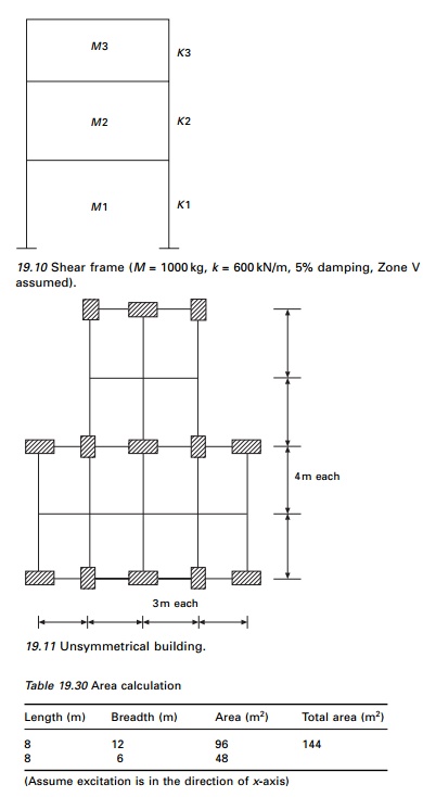
The final column shear and its direction due to direct shear and torsional moment are shown in Fig. 19.12.
Example 19.8
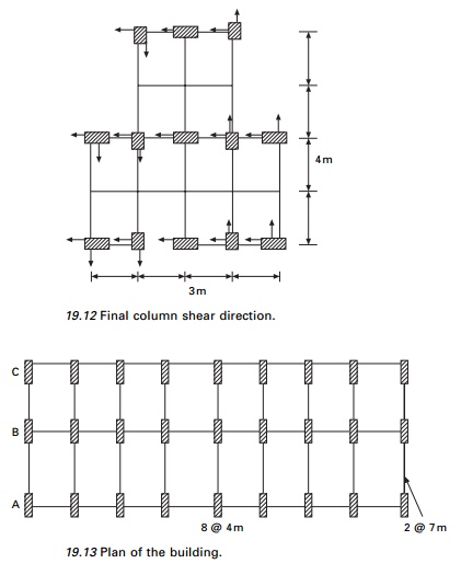
A six storey reinforced concrete building has a plan dimension as shown in Fig. 19.13. The size of exterior columns (9 each on lines A & C ) are 300 ├Ś 500 mm and interior column (9 on line B) is 300 ├Ś 600 mm for the lower three floors and respectively 300 ├Ś 400 mm and 300 ├Ś 500 mm for the upper three floors. The height between floors is 3.5 m. Dead load/unit area of floor which consist of floor slab, half the weight of column above and below the floor, partition walls, etc., are assumed to be 5 kN/m2. The intensity of live load is assumed to be 3 kN/m2. The soil below is hard and the building is located in Delhi.
Solution
Equivalent lumped weight at various floors:
The load on all floors except roof = 5 + 0.25 ├Ś 3 = 5.75 kN/m2
Load on roof = 5 kN/m2
Plan area = 14 ├Ś 32 = 448 m2
Equivalent weight on each floors except roof = 5.75 ├Ś 448 = 2576 kN
Equivalent weight on roof = 5 ├Ś 448 = 2240 kN Total wt = 5 ├Ś 2576 + 2240 = 15 120 kN
(A) Empirical method
To find natural period (T)
From clause 7.6.1 T1 = 0.075 h0.75
= 0.075 ├Ś 210.75
= 0.735; Ta = 0.505
(B) Horizontal seismic coefficient
Delhi is in Zone IV and Z = 0.24; I = 1; R = 3; Sa/g = 1/T
= 0.0792
Base shear = 0.0792 ├Ś 15120
=1197 kN
Lateral load and shear force at various levels are calculated as shown in Table 19.38 and shown in Fig. 19.14.
By modal superposition method, Assume the frame as shear frame for the calculation of periods
K = 12EI/h3; h = 3.5 m; E = 20 ├Ś 109 N/mm2
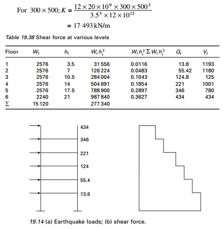
For col 300 ├Ś 600 K = 30 228 kN/m For
col 300 ├Ś 400 K = 8956.4 kN/m
In the lower three floors there are 18 columns of size 300 ├Ś 500 and 9 of 300 ├Ś 600 and columns are acting parallel.
K = 18 ├Ś 17 493 + 9 ├Ś 30 228 = 586 926 kN/m
For upper three floors K = 18 ├Ś 8956.4 + 9 ├Ś 17 493
= 318 652 kN/m
The equivalent column stiffness and mass along the shorter direction are given in Table 19.39.
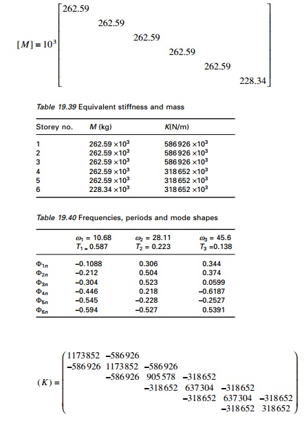
Using the MATHEMATICA package, periods and mode shapes can be calculated as shown in Table 19.40.
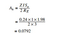
Earthquake response: design horizontal seismic coefficient Ah
Ah = Z I Sa 2 Rg
![]()
Z = 0.24; I = 1, R = 3
Ah values are given in Table 19.41.
Modal mass and modal participation factor:
Modal mass and participation factors are calculated in Table 19.42.
Weight in first mode = 54902/2451 = 12 296
%wt in 1st mode = 12 296/15 120 = 0.813 Weight in 2nd mode = 22272/2478 = 2001
%wt in 2nd mode = 2001/15 120 = 0.1324 Weight in 3rd mode = 8942/2423 = 330
%wt in 3rd mode = 330/15 120 = 0.021 Participation factor (pk)
P1 = ŌĆō5490/2451 = ŌĆō2.239
P2 = 2227.5/2478.6 = 0.898
P3 = 894/2423 = 0.36
Design lateral force and storey shear in each mode
Lateral force Qik = AhPkWiŽåik
Lateral forces are calculated as shown in Table 19.43.
Base shear 874 kN by modal analysis is less than VB = 1195 kN and as per clause 7.8.2 all the response quantities must be multiplied by 1195/874 = 1.367 and the shear is calculated as shown in Table 19.43. Drift calculations are given in Table 19.44.
Example 19.9
An eight storey RC framed building shown in Fig. 19.15 with live load of 3 kN/m2 is to be constructed in Coimbatore. Work out seismic forces in the structure. All beams and columns assumed to be 250 ├Ś 400 mm and 400 ├Ś 500 mm respectively. The roof and floor slabs are assumed to be 150 mm thick. The walls all around are 120 mm thick. H = 3 m.
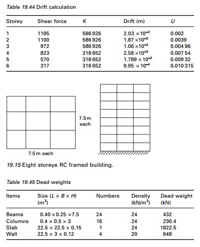
Solution
Step 1: Dead weights are shown in Table 19.45. Imposed load at all floors except roof:
(25% of imposed load for 3 kN/m2 ŌĆō see Table 19.8 of IS1893 2002) = 22.5 ├Ś 22.5 ├Ś 3├Ś 0.25 = 379.7 kN
Lumped mass at floor level except roof
W = 432 + 230.4 + 1822.5 + 648 + 379.7 = 3512.6 kN Lumped mass at roof level:
W = 432 + 230/2 + 1822.5 + 648/2 = 2693.7 kN
Step 2: Base shear calculation
Total gravity load on building = 7 ├Ś 3512.6 + 2693.7 = 27 281.9 kN
According to clause 7.6.2 the fundamental natural period of vibration
Z = 0.16 I = 1 R = 3
Ah = (0.16/2) ├Ś (1/3) ├Ś 2.5
= 0.067
Base shear VB = Ah ├Ś w
=0.067 ├Ś 272 81.9
=1827.8 kN
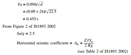
Step 3: Distribution of shear force is given in Table 19.46.
Example 19.10
A 15 storey RC framed building (30 m ├Ś 22.5 m in plan) with live load of 2 kN/m2 soil below is hard. The site lies in Zone V. All beams are of size 400 ├Ś 500 mm and columns are 600 ├Ś 600 mm. The spacing of columns is 7.5 m. Slabs are assumed to be 150 mm thick. The walls all around is 120 mm thick. Also analyse for soft soils.
Solution
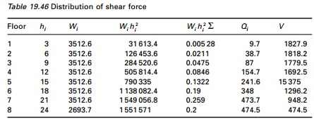
Calculation of dead loads is shown in Table 19.47.
Imposed load at all floors except roof:
(25% of imposed load for 2 KN/m2 ŌĆō see Table 8 of IS1893 2002)
= 22.5 ├Ś 30 ├Ś 2 ├Ś 0.25 = 337.5 kN
Total load on all floors except roof = 4810.40 + 337.5 = 5147.9 kN
Roof = 1116 + 518.4/2 + 2420 +756/2 = 4173.20 kN
Stiffness of 20 columns = K
= 20 ├Ś 12 ├Ś 18.8 ├Ś 103├Ś 1.08 ├Ś 1010/30003
= 1 804 800 kN/m
To find natural frequencies
Using the MATHEMATICA or MATLAB package
Žē1 = 6.029 rad/s, Žē2 = 18.05 rad/s, Žē3 = 29.91 rad/s
T1 = 1.042 s, T2 = 0.348 s, T3 = 0.21 s
Modal shapes at various floor levels are given in Table 19.48.
For Zone V; rock site (Z = 0.36); moment resisting frame (R = 5); (I = 1) we get A1 = 0.034 (rock), 0.0576 (soil); A2 = 0.09 (both); A3 = 0.09 (both) and modal participation factors are P1 = 3.57; P2 = 1.18; P3 = 0.692 and the percentage of modal mass participating to various modes in percentages are 83.7%, 14%, 3.4% respectively.
Calculations are carried out as per the code and finally the shear in each floor may be carried out and given in Table 19.49 for first mode only after modification as shown below.
Calculation of base shears using fundamental period.
Rock X direction:
VB = Ah W = 0.048 ├Ś 76243.8 = 3650 kN > 2270 kN
![]()
Hence all shears are to be multiplied by 3650/2270 = 1.61. For soft soil similar calculations are carried out and the multiplying factor is 6085/3659 = 1.66.
Allowable drift in each storey = 3000/400 = 7.5 mm
Hence actual drift is less then allowable drift (Program 19.1 can be used)
Related Topics