Chapter: Civil : Structural dynamics of earthquake engineering
Codal provisions for seismic design
Codal provisions
for seismic design
1 International Building Code of USA 2000
The base shear is given by
Vb = CsW --- 19.4
where W is the total
weight and applicable portions of other loads and the seismic coefficient CS
is given by

This coefficient corresponding to
R = 1 is known as the elastic seismic coefficient.
Ce =
IC --- 19.6
where I is the importance
factor: I = 1 for most structures, I = 1.25 for structures
that have substantial public hazard due to occupancy and I = 1.5 for
essential facilities that are required for post earthquake recovery.
The period coefficient C
depends on the location of the structures and site class.

where T1 is the
fundamental natural vibration period of the structure in seconds

where wi is the
weight of the ith floor and ui are the floor
displacements due to static application of a set of lateral loads Fi
at floor levels i = 1, 2, 3,ŌĆ”,N. These forces Fi
may be any reasonable distribution over the building height and need not be
exactly the design lateral forces specified in the code.
The response modification factor R
depends on several factors, including ductility capacity and inelastic
performance of structural materials and systems during past earthquake. Specified
values of R vary between 1.5 and 8.
The distribution of lateral force
over the height of building is given by
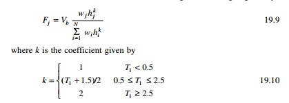
The deterministic overturning
moments are multiplied by a factor J. J = 1.0 for the top 10
storeys, 1ŌĆō0.8 for next ten storeys from top and varying linearly with the
height 0.8 for remaining floors.
2 New Zealand
Standards NZS 1170.5
Seismic design in New Zealand has
evolved over the past 30 years from an ŌĆśallowable stress basisŌĆÖ to ŌĆśstrength
capacityŌĆÖ approach. The concept of ŌĆśCapacity designŌĆÖ is well
established as a way of thinking for New Zealand structural engineers and
dominates their design approach. Over the past 15 years, the loading standards
(NZS 4203-92, NZS 1170.5) have been used as a basis of design a ŌĆśconstant
hazard design spectrumŌĆÖ. The spectra is not intended to be an ŌĆśearthquakeŌĆÖ
spectrum but a spectrum for which the acceleration at each spectral period
has an equal likelihood of being exceeded over some passage of time. New
Zealand design spectra are anchored back to a constant hazard approach.
The forces acting on a structure
as a result of ground shaking are usually determined by one of the following
methods:
ŌĆó Static
analysis: using equivalent static force obtained from acceleration response
spectra from horizontal earthquake motions.
ŌĆó Dynamic
analysis: either the modal response spectrum method or numerical integration
time history method using earthquake records:
According to New Zealand standard
for general structural design loading for buildings the equivalent static
method of analysis can be applied only where at least one of the following
criteria is satisfied:
ŌĆó The
height between the base and top of the structure does not exceed 15 m.
ŌĆó The
calculated fundamental period of vibration of the structure does not exceed
0.45 s.
ŌĆó The
structure satisfies the horizontal and vertical regularities requirement
standard and has a fundamental period of vibration <2 s.
According to NZS 4203:1993[1.3]
when the equivalent static force method is used, the design horizontal seismic
forces acting at the base of the structure or at the serviceability limit state
is

Ch(T1, ┬Ą) = basic
seismic horizontal coefficient which depends on fundamental period of
vibration T1, required structural ductility factor ┬Ą of the structure.
Ch(T1, 1)
= basic seismic hazard coefficient when ┬Ą = 1. Sp ŌĆō
structural performance factor, R ŌĆō risk factor, Z ŌĆō zone
factor to take into account regional seismicity, Wt ŌĆō weight
of structure and contents considered to be present during earthquake.
The horizontal seismic design force V given
by Eqs 19.11 and 19.12 are distributed appropriately up to the height of the
structure. ┬Ą is the structural ductility
factor given by Ōłåmax/Ōłåy.
According to NZS 4203: 1992 (1.3) structural
performance factor SP is taken as 2/3 unless specified
otherwise in the material standard. A value of 2/3 is justified as a result of
beneficial effects.
In some structures Sp Ōēł 1 may be more appropriate. The risk factor R
varies between 1.3 for buildings dedicated to the preservation of human life or
for which loss function would have a severe impact on society and 0.6 for
buildings of secondary importance with a range of values between. The zone
factor Z varies between 0.6 and 1.2. For most of the New Zealand zones,
the value of Z corresponds to approximately to 5% damped spectral
acceleration coefficient at a fundamental period of vibration of 0.2 s of 450
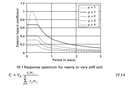
year return period uniform risk hazard spectra for elastic response. Figure
19.1 shows the response spectrum for the basic hazard acceleration coefficient
for near or very stiff soil recommended by NZS-4203: 1992[3].
The above elastic response spectra for ultimate
limit state have an assured return period of 450 years (approximately 10% of
probability of exceedence in 50 years). NZS 3101: 1995[1.5] specifies values
for displacement factors and design procedures for various categories of
ductility of reinforces concrete (RC) structures.
3 Eurocode 8 procedure (EC-8)
The method is referred to as
ŌĆśsimplified modal response spectrum analysisŌĆÖ rather than ŌĆśequivalent static
analysisŌĆÖ and is restricted to structures that are not significantly affected
by higher modes and/or stiffness irregularities. The base shear is calculated
as
VB = Sd(T1)W --- --19.13
Sd(T1)
is the ordinate of the design spectrum corresponding to fundamental period
T1 of the structure and W is the gravity load
contributing W.
The inertia forces are taken as
permanent loads G and portion ŽłEQ of
variable live loading Q. The fundamental period T1 can
be estimated for a proper eigen value analysis or from empirical formula
included in the code.
The lateral force corresponding
to VB can be calculated as
where Fi is the
horizontal force acting in storey i, si and sj
are displacement of masses mi, mj in the
fundamental mode shape. The code assumes the fundamental mode shape is
increasing linearly with the height of the building, hence si
is substituted for zi.
In order to cover uncertainties
in the distribution of mass and stiffness as well as spatial variability of
ground motion, an accidental eccentricity of the loads Fi
with respect to mass centre CM of the storey has to be
introduced in the analysis and is equal to
e1i = ┬▒0.05Li 19.15
where Li is the
floor dimension perpendicular to the direction of force Fi.
The eccentricity e1 is additional to any existing
eccentricity e0 between the stiffness centre CS
and mass centre CM at any storey. Hence torsional moment
Mt = Fi(e0 + e1)
or simply Fie1 if a three-dimensional model
is used to act at the mass centre. The load combination including
seismic loading is

ŌĆś+ŌĆÖ means to be combined with; G
= permanent dead load; Q = variable imposed load; ╬│1
important factor; Ed design value for seismic action.
The criterion for the required
number of modes to be included in the analysis is two-fold:
1. The sum
of effective modal mass should amount to at least 90% of the total mass.
2. All modes
with effective mass >5% of the total mass should be considered.
The modal action should be
combined with SRSS unless the period of two of them considered modes differ by
less than 10%, in which case CQC approach should be used.
4 Uniform Building
Code (UBC) 1997
The method is applicable to all
buildings in the low seismicity zone (zone 1 and usual structures in seismic
zone 2), regular structures up to 73 m and irregular structure having no more
than five stories. The design base shear is given by

W = seismic
dead load, Ca, Cv I and R define the
design spectrum. The seismic coefficients Ca, Cv
of 1997 UBC are given in Table 19.2.
The load factor in the above
equations should be increased by 10% for design of RC and masonry structures.
There are two differences in the modal analysis procedure specified in UBC:
1. The
elastic rather than the design response spectrum is used for estimating actual
effect.
2. The
elastic force calculated above is then scaled down to account for inelastic
effects. This is done by adjusting them to 90% of VB used in
the equivalent stated analysis in the case of regular structures 100% in case
of irregular structures.
5 National Building Code (NBC) of Canada (1995)
The base shear is expressed as
VB = CsW -----19.22
The seismic coefficient Cs
is given by

U = 0.6 is
a calibration factor applied to maintain the design base shear at the
same level of protection (as in the preceding edition of the code) for
buildings with good to excellent capability of resisting seismic loads. The
elastic seismic coefficient is given by

1. Zonal
velocity factor ╬│ varies
between 0 for least seismic zone to 0.4 and the worst seismic zone.
2. I = 1.5,
1.3 and 1 for post-disaster building, for schools and for other buildings
respectively.
3. F = 1.0,
1.3, 1.5, 2.0 foundation factors depending on soil category.
4. S =
seismic response factor varies with T1
For T1 < 0.5
s

Za, Zv represent
acceleration-related seismic zones and velocity-related seismic zones
respectively. Canada is divided into seven zones based on each of the two
criteria.
The empirical formula for
calculating T1 is

where ui is the
floor displacement of ith floor, wi is a set of
lateral loads at floor levels. The elastic seismic coefficient Ce
depends on pseudo-acceleration design spectrum scaled to ground velocity of 0.4
m/s (╬│ = 0.4).

The force modification factor R
varies from 1 for brittle structure to 4 for ductile moment
resisting space frames.
The distribution of lateral
forces over the height of the building is determined from
The National Building Code of
Canada (NBC) was revised in 2005. The seismic hazard map is given and the
seismic hazard is expressed as the most powerful ground motion that is likely
to occur in an area for a given probability level. Building design for various
earthquake loads is addressed in Sections 4.1.8, 9.20.1.2, 9.23.10.2 and
9.31.6.2 of the 2005 NBC. The seismic hazard values are described by spectral
acceleration values at periods 0.2, 0.5, 1.0 and 2.0 s. It is a better measure
of potential damage than the peak measure used by 1995 and thus improves
earthquake design. PGA is still used in foundation design. The probability used
in the 2005 NBC is 0.000404 per annum equivalent to 2% probability exceeding
over 50 years. A building designed to tolerate a sideward pushing force
equivalent to 40% of it own weight should prove earthquake-resistant.
6 Mexican Federal
District Code (MFDC) 1993
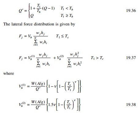
The seismic coefficient is
calculated as
Cs
=
Ce/QŌĆ▓ ---19.33
Elastic seismic coefficient
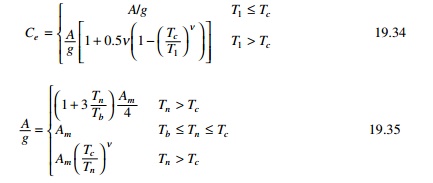
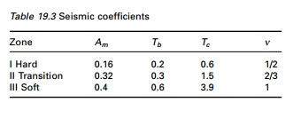
T1 Fundamental
time period, Tb and Tc = beginning and end
of constant acceleration regions, Am, ╬Į, Tb, Tc
are given in Table 19.3.
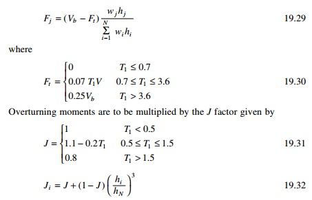
The elastic seismic coefficient
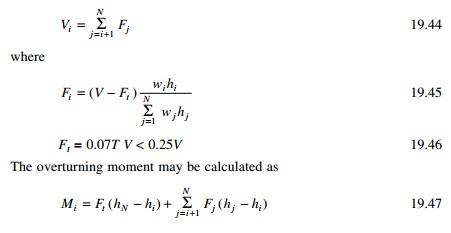
Overturning moments determined are multiplied by reduction
factor that varies linearly from 1.0 at the top of the building to 0.8 at its
base to obtain design values.
7 Japanese Society
of Civil Engineers (JSCE) 2000
All codes except the JSCE code
basically apply the concepts of the capacity design philosophy. Although the JSCE
code does not follow the capacity design principles, it should be noted that
basic ideas of seismic design are essentially similar and the JSCE code does
not prescribe any specific design earthquake motion. The seismic code of
buildings in Japan was revised in June 2000 to implement a performance-based
structural engineering framework. The code provides the performance objectives,
life safety and damage limitation of a building at the two
corresponding levels of earthquake.
Design response spectra at engineering bedrock
The earthquake ground motion used for the seismic design at
the life safety limit is the site-specific motion of an extremely rare
earthquake which is expected to occur once in approximately 500 years. The
engineering bedrock is assumed to be the soil layer whose shear wave velocity
is >400 m/s. The basic design earthquake acceleration response spectra S0
of the seismic ground motion at the exposed outcrop engineering bedrock is
given as

where S0 =
basic design acceleration response spectra in m/s2 and T =
natural period. The level of earthquake ground motion used for the seismic
design at the damage limit should be reduced to one-fifth of life safety.
Design response spectra at ground motion
Sa(T) = Gs(T)
Z S0(T) ---19.40
Where
Sa = design acceleration
response spectra at ground surface m/s2, Gs =
surface soil layer amplification factor, Z = seismic zone factor
0.7 to 1.0 and T = natural period.
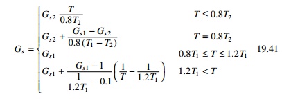
Gs1 = Gs ratio at T1
Gs2 =
Gs ratio at T2
T1 = predominant
period of surface soil layer for first mode T2 =
predominant period of surface soil layer for second mode Minimum values
of Gs

8 Iranian code
Almost everywhere in Iran is
prone to earthquake as two major earthquake belts run through the country.
Every decade or so a major earthquake strikes Iran, resulting in many
fatalities and collapsed buildings. Traditional Iranian buildings, especially
in the rural areas, have very little resistance to earthquakes of higher
magnitude.
After numerous major earthquakes,
in particular that of 1963 in Bouein Zahra, the Iranian government began the
preparation of code of practice for earthquake protection in 1967. IranŌĆÖs
Ministry of Housing first published a code of practice for earthquake-resistant
construction which requires buildings taller than 11 m to be made of RC or
steel frames.
In 1993 the Iranian Building Research Centre further revised
the code and after three stages of research, construction and design and the
updated and revised Iranian code for seismic resistant design was published in
1997 (IS2800). This code was revised in 1999 and covers seismic design of RC
and steel and masonry construction. According to IS2800 (1999) chapter 2, the
seismic base shear coefficient is obtained from

where
V = base shear
w = total weight of the building (DL+0.2LL)
C = base shear coefficient
A = design base acceleration or
ratio to gravity which may be 0.2, 0.25, 0.3, 0.35 depending on regions
(0.3g for Bamm in region 2 of the seismic micro-organization map of
Iran)
B =
building response factor obtained from design response spectrum (amplification
factor)
I =
importance factor of the building = 0.8, 1.0 or 1.2 T = natural period
of the building
T0 = corner
period of the acceleration response spectrum dependent on soil type (0.4
0.5 0.7 1.0) 0.5 s for soil type in Bamm
R =
building factor varying from 4 to 11 (for example, 4 for simple masonry with
frame 6 for concentric steel-braced buildings)
H = height of the building from
base in m
For a two storey masonry building B = 2.5, I =
1, R = 4, the base shear coefficient C is estimated as 0.19.
Seismic lateral forces may be calculated from
9 Chinese code
Before 1964 there was no
seismic-resistant design code for buildings and other structures in China.
Earthquake-resistant design was not considered for most buildings. A draft of
seismic-resistant design code in China was prepared in 1964. The first official
seismic code of China was issued in 1974. In 1975 and 1976 China suffered two
strong earthquakes: 1975 earthquake of Haichung with a magnitude of 7.3 and
Tangshan with a magnitude of 7.8. These two earthquakes were considered to be
catastrophic disasters, killing 242 829 people. The code was revised and put
into effect in 1993. Equivalent lateral force method was recommended.
The total horizontal seismic action FEK
(base shear) is given by

where weq is the total equivalent seismic
weight of a building and ╬▒ is the
seismic coefficient which can be determined from

where Tg is the
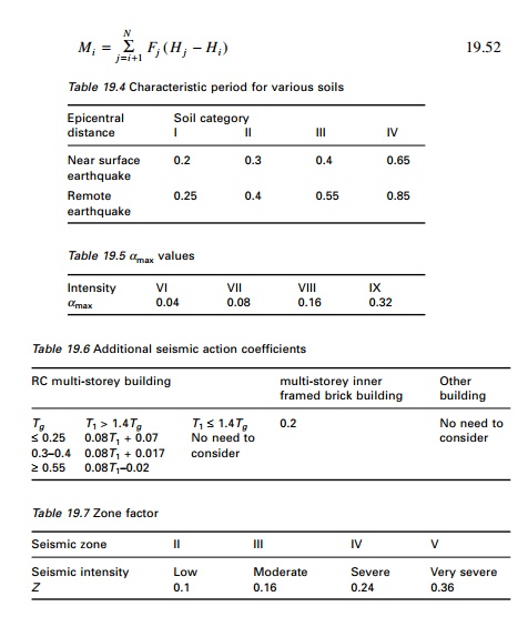
characteristic period of vibration of the soil given in Table 19.4
The total seismic weight should
be used when the structure is modelled as a single-degree-of-freedom (SDOF)
system, 85% of total seismic weight if it is modelled as a
multiple-degrees-of-freedom (MDOF) system. Table 19.5 gives values of ╬▒max.
The horizontal seismic force Fi applied at
any level I of the building is given by
where ╬┤N is
called additional seismic action coefficient given in Table 19.6. The overturning
moment is given as
For any other country code one
may refer to the international handbook of earthquake engineering codes by
Maria Paz (1994).
10Indian Seismic Code 1893 ŌĆō Part 1 ŌĆō 2002
The first Indian Seismic Code
(IS 1893) was first published in 1962 and it has since been revised in 1966,
1970, 1975 and 1984. More recently it was decided to split this code into a
number of parts and Part 1 of the code containing general provisions
(applicable to all structures) and specific provisions for buildings has been
published. Some extracts of the code are given below.
The design horizontal seismic coefficient Ah
for a structure can be determined from

Provided that for any structure
with T Ōēż 0.1 s
the value of Ah will not be less than Z/2 whatever may
be the value of I/R.
Z = zone
factor as given in Table 19.7 and it is for a maximum considered earthquake (MCE)
and service life of structure in a zone. The factor 2 is used in the
denominator to reduce MCE to design basis earthquake (DBE). I =
importance factor depending upon the functional use of the structure characterized
by hazardous consequences of its failure varying from 1 to 1.5. R =
response reduction factor depending on the perceived seismic damage performance
of the structure characterized y ductile or brittle deformations. However, the
ratio of I/R Ōēż 1.
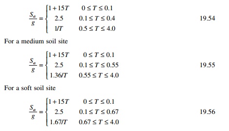
Sa/g ŌĆō average
response acceleration coefficient for rock or soil sites given by for 5%
damping. For rocky or hard soil
The response spectrum for
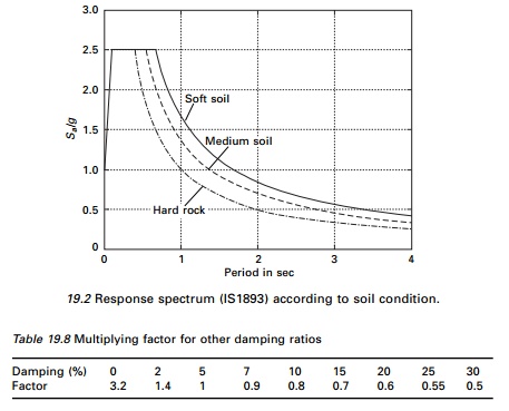
IS1893-2002 is shown in Fig. 19.2 and the zone factors are shown in Table 19.7.
Table 19.8 gives the multiplying factors for obtaining
spectral values for various other damping ratios.
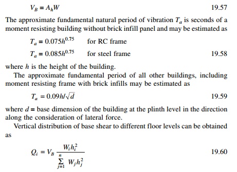
The seismic weight of each floor is its full dead load plus an
appropriate amount of imposed load. The total design lateral force or design
seismic base shear is given by
Dynamic analysis shall be performed to obtain the design seismic
force and its distribution to different levels along the height of the
building.
’éĢ Regular building >40 m in the zone IV and
V and >90 m in the height in Zones
II and III
’éĢ Irregular building. All framed buildings
>12 m in zones IV and V >40 m in
Zones II and III.
Dynamic analysis may be performed either by the time history
method or the response spectrum method. However, base shear VB
is compared with VB obtained by using approximate method. If VB
< VB all the
response quantities to be multiplied by VB /VB.
![]()
![]()
![]() Modal mass is calculated as
Modal mass is calculated as
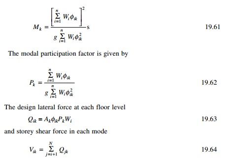
The peak storey shear force Vi
in each first storey due to all modes considered is obtained by combining those
due to each mode in accordance with square root of sum of squares (SRSS) or
complete quadratic combination (CQC) rules.
Program 19.1: MATLAB
program for IS1893 code
A program in MATLAB is written to
calculate the shear in each storey as well as drift calculations for a
multi-storey frame. Example 19.8 is solved by the MATLAB program and the
results are also given below.
% IS1893 - 2002, Part 1
multistorey buildings % calculation of shear in each storey and drifts nst=6;
m=zeros(nst,nst);
K=zeros(nst,nst);
ma=zeros(nst,1); ak=zeros(nst,1);
t=zeros(nst,1);
sa=zeros(nst,1);
pf=zeros(nst,1);
d=zeros(nst,nst);
v=zeros(nst,nst);
vv=zeros(nst,nst);
vr=zeros(nst,1);
ah=zeros(nst,1);
sf=zeros(nst,nst);
% ***************************************************
%input data %*****************************************************
%give masses for various floors starting from ground
ma(1,1)=262.59e3;ma(2,1)=262.59e3;ma(3,1)=262.59e3;ma(4,1)=262.59e3;
ma(5,1)=262.59e3;ma(6,1)=229.934e3;
%give stiffnesses for various floors starting from ground
ak(1,1)=586926e3;ak(2,1)=586926e3;ak(3,1)=586926e3;ak(4,1)=318652e3;
ak(5,1)=318562e3;ak(6,1)=318562e3;
%soil s=1 for rocky soil s=2 medium soil s=3 for soft soil
s=1;
%give zone number
zo=4;
% give damping % for concrete 5% for steel 2% etc
da=5;
% importance of the structure
is=1;
% response reduction factor
r=3;
% height of the building
ht=21;
% width of the building
width=14;
%it=1 for rc frame buildig without brick infil panel
%it =2 for steel frame building with out brick infil panel
%it=3 for all buildings with brick infill panel
it=3;
% *******************************************************
% input completed
%********************************************************
if zo==2
z=0.1;
end
if zo==3
z=0.16;
end
if zo==4 z=0.24;
end
if zo==5 z=0.36;
end
fid=fopen(ŌĆśoutput.tableŌĆÖ,ŌĆśwŌĆÖ); fprintf(fid,ŌĆśzone = %2i\nŌĆÖ,zo);
fprintf(fid,ŌĆśsoil=%2i\nŌĆÖ,s);
fprintf(fid,ŌĆśimportance factor=%2i\nŌĆÖ,is);
fprintf(fid,ŌĆśresponse reduction
factor=%2i\nŌĆÖ,r); fprintf(fid, ŌĆśstorey mass\nŌĆÖ);
for i=1:nst
fprintf(fid,ŌĆś%2i ,
%f\nŌĆÖ,i,ma(i,1)); end
fprintf(fid,ŌĆś storey
stiffness\nŌĆÖ); for i=1:nst
fprintf(fid,ŌĆś%2i,%f\nŌĆÖ,i,ak(i,1));
end
ak(nst+1,1)=0.0; nstm1=nst-1;
weight=0.0;
for i=1:nstm1 ip1=i+1; m(i,i)=ma(i,1);
K(i,i)=ak(i,1)+ak(ip1,1); K(i,ip1)=-ak(ip1,1);
weight=weight+m(i,i)*9.81;
end K
m(nst,nst)=ma(nst,1);
K(nst,nst)=ak(nst,1);
weight=weight+ma(nst,1)*9.81; for
i=1:nst
for j=i:nst K(j,i)=K(i,j);
end end m
K ki=inv(K); kim=ki*m;
[v,d]=eig(kim); for i=1:nst
for j=1:nst v(i,j)=v(i,j)/v(nst,j);
end end
for i=1:nst om(i,1)=1/sqrt(d(i,i));
t(i,1)=2*pi/om(i,1);
end
fprintf(fid,ŌĆśmode period\nŌĆÖ);
for i=1:nst fprintf(fid,ŌĆś%2i,%f\nŌĆÖ,i,t(i,1));
end
for j=1:nst
fprintf(fid,ŌĆśmode shape for mode = %2i\nŌĆÖ,j); for i=1:nst
fprintf(fid,ŌĆś%f\nŌĆÖ,v(i,j)); end
end if s<2
ml=0.4;
co=1; elseif (s>2)
ml=0.67;
co=1.67; else
ml=0.55;
co=1.36; end
for i=1:nst
if t(i,1)<0.1 sa(i,1)=1+15*t(i,1); elseif t(i,1)>ml
sa(i,1)=co/t(i,1);
else
sa(i,1)=2.5;
end end
if da==0 mf=3.2;
end
if da==2; mf=1.4;
end
if da==5; mf=1.0;
end
if da==7; mf=0.9;
end
if da==10; mf=0.8;
end
fprintf(fid,ŌĆś sa/g \nŌĆÖ); for
i=1:nst
sa(i,1)=mf*sa(i,1);
fprintf(fid,ŌĆś%f\nŌĆÖ,sa(i,1)); end
for i=1:nst sum=0.0; sum1=0.0; for j=1:nst
sum=sum+m(j,j)*v(j,i);
sum1=sum1+m(j,j)*v(j,i)^2; end
%sum
%sum1
pf(i,1)=sum/sum1;
pmas(i,1)=pf(i,1)*sum*9.81/weight;
end
fprintf(fid,ŌĆśmode participation
factor\nŌĆÖ); for i=1:nst
fprintf(fid,ŌĆś%2i,
%f\nŌĆÖ,i,pf(i,1)); end
fprintf(fid,ŌĆś percentage of modal
masses\nŌĆÖ); for i=1:nst
fprintf(fid,ŌĆś%2i,
%f\nŌĆÖ,i,pmas(i,1)); end
for i=1:nst ah(i,1)=z*is*sa(i,1)/(2.0*r);
if t(i,1)<0.1 & ah(i,1) <z/2
ah(i,1)=z/2;
end end
fprintf(fid,ŌĆśmode Ah\nŌĆÖ); for i=1:nst
fprintf(fid,ŌĆś%2i , %f\nŌĆÖ,i,ah(i,1)); end
for i=1:nst for j=1:nst
sf(j,i)=pf(i,1)*ah(i,1)*m(j,j)*v(j,i); end
end %sf
for j=1,nst vv(nst+1,j)=0.0;
end
for j=1:nst for i=1:nst
ii=nst-i+1; vv(ii,j)=sf(ii,j)+vv(ii+1,j);
end end
for i=1:nst for j=1:nst
vv(i,j)=9.81*vv(i,j); end
end
fprintf(fid,ŌĆÖ shear in various
stories for various modes\nŌĆÖ); for i=1:nst
fprintf(fid,ŌĆÖ for mode =%2i\nŌĆÖ,i); for j=1:nst
fprintf(fid,ŌĆÖ%2i %f\nŌĆÖ,j,vv(j,i)); end
end
for i=1:nst vr(i,1)=0.0; for j=1:nst
vr(i,1)=vr(i,1)+vv(i,j)^2; end
vr(i,1)=sqrt(vr(i,1)); end
fprintf(fid,ŌĆś base shear as per
modal calculation\nŌĆÖ); fprintf(fid,ŌĆś%f\nŌĆÖ,vr(1,1));
fprintf(fid,ŌĆś approximate
calculation as per the code\nŌĆÖ); if it==1
tn=0.075*ht^0.75; end
if it==2 tn=0.085*ht^0.75;
end
if it==3 tn=0.09*ht/sqrt(width);
end
fprintf(fid,ŌĆś fundamental natural
period = %f\nŌĆÖ,tn); if tn<0.1
saf=1+15*tn; elseif tn>ml saf=co/tn;
else saf=2.5;
end ahf=saf*z*is/(2*r); if
tn<0.1 & ahf <z/2
ahf=z/2; end ahf=ahf*mf; weight
vb=ahf*weight
fprintf(fid,ŌĆś base shear as per
codal approximate period %f\nŌĆÖ,vb); factor=vb/vr(1,1);
if factor>1 for i=1:nst
vr(i,1)=factor*vr(i,1); end
end
fprintf(fid,ŌĆś resultant shear in
various stories\nŌĆÖ); for i=1:nst
fprintf(fid,ŌĆś%2i
%f\nŌĆÖ,i,vr(i,1)); end
fprintf(fid,ŌĆś drift in various stories\nŌĆÖ); for
i=1:nst
dr(i,1)=vr(i,1)/ak(i,1); fprintf(fid,ŌĆś%2i %f \nŌĆÖ,i,dr(i,1));
end dr;
fclose(fid);
OUTPUT
zone = 4 soil= 1
importance factor= 1 response
reduction factor= 3 storey mass 1,262590.000000 2,262590.000000 3,262590.000000
4,262590.000000 5,262590.000000 6,229934.000000
storey stiffness
1,586926000.000000
2,586926000.000000
3,586926000.000000
4,318652000.000000
5,318562000.000000
6,318562000.000000 mode period
1,0.589328 2,0.223705 3,0.138951 4,0.072667 5,0.104123 6,0.093019
mode shape for mode = 1 0.182786
0.356276 0.511647 0.749899 0.917955 1.000000
mode shape for mode = 2 ŌĆō0.581337
ŌĆō0.957496 ŌĆō0.995713 ŌĆō0.418807 0.430599 1.000000
mode shape for mode = 3 0.641094
0.695710 0.113885 ŌĆō1.149675 ŌĆō0.475857 1.000000
mode shape for mode = 4
ŌĆō83.585291 112.412194 ŌĆō67.595631 17.300351 ŌĆō4.396286 1.000000
mode shape for mode = 5 ŌĆō1.155218
ŌĆō0.428418
0.996338
0.630861
ŌĆō1.628296
1.000000
mode shape for mode = 6 3.061088
ŌĆō0.126548 ŌĆō3.055856 3.038515 ŌĆō2.293290 1.000000
sa/g
1.696847
2.500000
2.500000
2.090004
2.500000
2.395278
mode participation factor 1,
1.329829 2, -0.472949 3, 0.210335 4, -0.001019 5, -0.110181 6, 0.043985
percentage of modal masses 1,
0.813473 2, 0.132582 3, 0.025087 4, 0.004336 5, 0.013297 6, 0.011226
mode Ah 1,0.067874 2,0.100000
3,0.100000 4,0.120000 5,0.100000 6,0.120000
shear in various stories for
various modes for mode = 1
1 835695.230296
2 793195.356194
3 710356.969254
4 591392.874440
5 417032.256536
6 203596.660163 for mode = 2
1 200671.454855
2 129845.975774
3 13192.337190
4 -108117.437477
5 -159141.610729
6 -106680.868269 for mode = 3
1 37970.806318
2 3234.813194
3 -34460.412555
4 -40630.981084 5 21661.132553 6 47444.203966 for mode = 4
1 7875.062753
2 -18466.077913
3 16959.597905
4 -4342.547766
5 1109.499737
6 -275.949577 for mode = 5
1 20126.010937
2 -12662.189159
3 -24821.840801
4 3456.897732 5 21362.427841 6 -24852.979108 for mode = 6
1 20389.068926
2 -21231.973689
3 -19511.317627
4 22038.591323 5 -19275.537688 6 11905.898799
base shear as per modal
calculation 860802.021330
approximate calculation as per the code
fundamental natural period = 0.505124
base shear as per codal
approximate period 1198572.993130 resultant shear in various stories
1 1198572.993130
2 1119971.883836
3 991684.516096
4 839604.037191
5 623536.713435
6 329037.218693 drift in various
stories
1 0.002042
2 0.001908
3 0.001690
4 0.002635
5 0.001957
6 0.001033
Related Topics