Chapter: Electrical machines : Transformer
Transformer: Principle of Operation
TRANSFORMER
Principle Of Operation
A transformer is a device that transfers electrical energy from one circuit to another through inductively coupled conductor. A varying current in the first or primary winding creates a varying magnetic flux in the transformer core, and thus a varying magnetic field through the secondary winding. This varying magnetic field induces a varying electromotive force EMF or voltage in the secondary winding. This effect is called mutual induction.
If a load is connected to the secondary, an electric current will flow in the secondary winding and electrical energy will be transferred from the primary circuit through the transformer to the load. In an ideal transformer, the induced voltage in the secondary winding is in proportion to the primary voltage , and is given by the ratio of the number of turns in the secondary to the number of turns in the primary as follows:
By appropriate selection of the ratio of turns, a transformer thus allows an alternating current (AC) voltage to be "stepped up" by making greater than , or "stepped down" by making less than .
Basic Principle
Construction
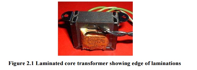
Laminated steel cores
Transformer use at power or audio frequencies typically have cores made of high permeability Si steel. The steel has permeability many times that of free and the core thus serves to greatly reduce the magnetizing current and confine the flux to a path which closely couples the windings. Early transformer developers soon realized that cores constructed from solid iron resulted in prohibitive eddy-current losses, and their designs mitigated this effect with cores consisting of bundles of insulated iron wires. Later designs constructed the core by stacking layers of thin steel laminations, a principle that has remained in use. Each lamination is insulated from its neighbors by a thin non-conducting layer of insulation. The universal transformer equation indicates a minimum cross-sectional area for the core to avoid saturation.
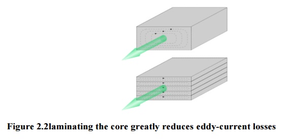
The effect of laminations is to confine eddy currents to highly elliptical paths that enclose little flux, and so reduce their magnitude. Thinner laminations reduce losses, but are more laborious and expensive to construct. Thin laminations are generally used on high frequency transformers, with some types of very thin steel laminations able to operate up to 10 kHz.
One common design of laminated core is made from interleaved stacks of E- shaped steel sheets capped with shaped pieces, leading to its name of "E-I transformer”. Such a design tends to exhibit more losses, but is very economical to manufacture. The cut-core or C-core type is made by winding a steel strip around a rectangular form and then bonding the layers together. It is then cut in two, forming two C shapes, and the core assembled by binding the two C halves together with a steel strap.They have the advantage that the flux is always oriented parallel to the metal grains, reducing reluctance.
A steel core's permanence means that it retains a static magnetic field when power is removed. When power is then reapplied, the residual field will cause a high inrush until the effect of the remaining magnetism is reduced, usually after a few cycles of the applied alternating current. Over current protection devices such as fuses must be selected to allow this harmless inrush to pass. On transformers connected to long, overhead power transmission lines, induced currents due to geomagnetic disturbances during solar storms can cause saturation of the core and operation of transformer protection devices.
Distribution transformers can achieve low no-load losses by using cores made with low-loss high-permeability silicon steel oramorphous (non-crystalline) metal alloy. The higher initial cost of the core material is offset over the life of the transformer by its lower losses at light load.
Solid cores
Powdered iron cores are used in circuits such as switch-mode power supplies that operate above mains frequencies and up to a few tens of kilohertz. These materials combine high magnetic permeance high bulk electrical resistivity. For frequencies extending beyond the VHF band, cores made from non-conductive magnetic ceramic materials called ferrites are common. Some radio-frequency transformers also have movable cores (sometimes called 'slugs') which allow adjustment of the coupling coefficient (and bandwidth) of tuned radio-frequency circuits Toroidal transformers are built around a ring-shaped core, which, depending on operating frequency, is made from a long strip of silicon steel or perm alloy wound into a coil, powdered iron, or ferrite. A strip construction ensures that the grain boundaries are optimally aligned, improving the transformer's efficiency by reducing the core'sreluctance. The closed ring shape eliminates air gaps inherent in the construction of an E-I core.[78] The cross-section of the ring is usually square or rectangular, but more expensive cores with circular cross-sections are also available. The primary and secondary coils are often wound concentrically to cover the entire surface of the core. This minimizes the length of wire needed, and also provides screening to minimize the core's magnetic field from generating electromagnetic.
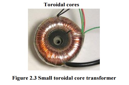
Toroidal transformers are more efficient than the cheaper laminated E-I types for a similar power level. Other advantages compared to E-I types, include smaller size (about half), lower weight (about half), less mechanical hum (making them superior in audio amplifiers), lower exterior magnetic field (about one tenth), low off-load losses (making them more efficient in standby circuits), single-bolt mounting, and greater choice of shapes. The main disadvantages are higher cost and limited power capacity (see "Classification" above). Because of the lack of a residual gap in the magnetic path, toroidal transformers also tend to exhibit higherinrush current, compared to laminated E-I types.
Ferrite toroidal cores are used at higher frequencies, typically between a few tens of kilohertz to hundreds of megahertz, to reduce losses, physical size, and weight of a switched-mode power supply. A drawback of toroidal transformer construction is the higher labor cost of winding. This is because it is necessary to pass the entire length of a coil winding through the core aperture each time a single turn is added to the coil. As a consequence, toroidal transformers are uncommon above ratings of a few kVA. Small distribution transformers may achieve some of the benefits of a toroidal core by splitting it and forcing it open, then inserting a bobbin containing primary and secondary windings.
Air cores
A physical core is not an absolute requisite and a functioning transformer can be produced simply by placing the windings near each other, an arrangement termed an "air-core" transformer. The air which comprises the magnetic circuit is essentially lossless, and so an air-core transformer eliminates loss due to hysteresis in the core material. The leakage inductance is inevitably high, resulting in very poor regulation, and so such designs are unsuitable for use in power distribution. They have however very high bandwidth, and are frequently employed in radio-frequency applications, for which a satisfactory coupling coefficient is maintained by carefully overlapping the primary and secondary windings. They're also used for resonant transformers such as Tesla coils where they can achieve reasonably low loss in spite of the high leakage inductance.
Windings
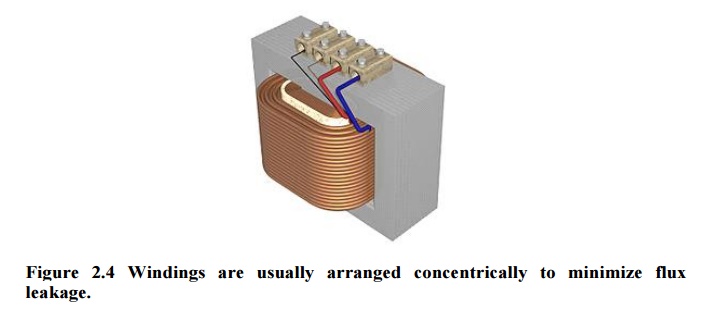
The conducting material used for the windings depends upon the application, but in all cases the individual turns must be electrically insulated from each other to ensure that the current travels throughout every turn.For small power and signal transformers, in which currents are low and the potential difference between adjacent turns are there.
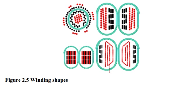
Cut view through transformer windings. White: insulator. Green spiral: Grain oriented silicon steel. Black: Primary winding made ofoxygen-free copper. Red: Secondary winding. Top left: Toroidal transformer. Right: C-core, but E-core would be similar. The black windings are made of film. Top: Equally low capacitance between all ends of both windings. Since most cores are at least moderately conductive they also need insulation. Bottom: Lowest capacitance for one end of the secondary winding needed for low-power high-voltage transformers. Bottom left: Reduction of leakage would lead to increase of capacitance.
Large power transformers use multiple-stranded conductors as well, since even at low power frequencies non-uniform distribution of current would otherwise exist in high-current windings. Each strand is individually insulated, and the strands are arranged so that at certain points in the winding, or throughout the whole winding, each portion occupies different relative positions in the complete conductor. The transposition equalizes the current flowing in each strand of the conductor, and reduces eddy current losses in the winding itself. The stranded conductor is also more flexible than a solid conductor of similar size, aiding manufacture.
For signal transformers, the windings may be arranged in a way to minimize leakage inductance and stray capacitance to improve high-frequency response. This can be done by splitting up each coil into sections, and those sections placed in layers between the sections of the other winding. This is known as a stacked type or interleaved winding.
Power transformers often have internal connections or taps at intermediate points on the winding, usually on the higher voltage winding side, for voltage regulation control purposes. Such taps are normally manually operated, automatic on-load tap changersbeing reserved, for cost and reliability considerations, to higher power rated or specialized transformers supplying transmission or distribution circuits or certain utilization loads such as furnace transformers. Audio-frequency transformers, used for the distribution of audio to public address loudspeakers, have taps to allow adjustment of impedance to each speaker. A center is often used in the output stage of an audio power amplifier in a push-pull circuit. Modulation transformers in AM transmitters are very similar.Certain transformers have the windings protected by epoxy resin. By impregnating the transformer with epoxy under a vacuum, one can replace air spaces within the windings with epoxy, thus sealing the windings and helping to prevent the possible formation of corona and absorption of dirt or water. This produces transformers more suited to damp or dirty environments, but at increased manufacturing cost.
Cooling
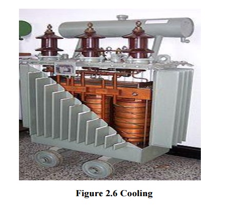
Cutaway view of oil-filled power transformer. The conservator (reservoir) at top provides oil-to-atmosphere isolation. Tank walls' cooling fins provide required heat dissipation balance.
Though it is not uncommon for oil-filled transformers to have today been in operation for over fifty years high temperature damageswinding insulation, the accepted rule of thumb being that transformer life expectancy is halved for every 8 degree C increase in operating temperature. At the lower end of the power rating range, dry and liquid-immersed transformers are often self-cooled by natural convection and radiation heat dissipation. As power ratings increase, transformers are often cooled by such other means as forced-air cooling, force-oil cooling, water-cooling, or a combinations of these. The dialectic coolant used in many outdoor utility and industrial service transformers is transformer oil that both cools and insulates the windings. Transformer oil is a highly refinedmineral oil that inherently helps thermally stabilize winding conductor insulation, typically paper, within acceptable insulation temperature rating limitations. However, the heat removal problem is central to all electrical apparatus such that in the case of high value transformer assets, this often translates in a need to monitor, model, forecast and manage oil and winding conductor insulation temperature conditions under varying, possibly difficult, power loading conditions. Indoor liquid-filled transformers are required by building regulations in many jurisdictions to either use a non-flammable liquid or to be located in fire-resistant rooms. Air-cooled dry transformers are preferred for indoor applications even at capacity ratings where oil-cooled construction would be more economical, because their cost is offset by the reduced building construction cost.
The oil-filled tank often has radiators through which the oil circulates by natural convection. Some large transformers employ electric-operated fans or pumps for forced-air or forced-oil cooling or heat exchanger-based water-cooling. Oil-filled transformers undergo prolonged drying processes to ensure that the transformer is completely free of water before the cooling oil is introduced. This helps prevent electrical breakdown under load. Oil-filled transformers may be equipped with Buchholz relays, which detect gas evolved during internal arcing and rapidly de-energize the transformer to avert catastrophic failure. Oil-filled transformers may fail, rupture, and burn, causing power outages and losses. Installations of oil-filled transformers usually include fire protection measures such as walls, oil containment, and fire-suppression sprinkler systems.
Insulation drying
Construction of oil-filled transformers requires that the insulation covering the windings be thoroughly dried before the oil is introduced. There are several different methods of drying. Common for all is that they are carried out in vacuum environment. The vacuum makes it difficult to transfer energy (heat) to the insulation. For this there are several different methods. The traditional drying is done by circulating hot air over the active part and cycle this with periods of hot-air vacuum (HAV) drying. More common for larger transformers is to use evaporated solvent which condenses on the colder active part. The benefit is that the entire process can be carried out at lower pressure and without influence of added oxygen. This process is commonly called vapor-phase drying (VPD).
For distribution transformers, which are smaller and have a smaller insulation weight, resistance heating can be used. This is a method where current is injected in the windings to heat the insulation. The benefit is that the heating can be controlled very well and it is energy efficient. The method is called low-frequency heating (LFH) since the current is injected at a much lower frequency than the nominal of the grid, which is normally 50 or 60 Hz. A lower frequency reduces the effect of the inductance in the transformer, so the voltage needed to induce the current can be reduced. The LFH drying method is also used for service of older transformers.
Terminals
Very small transformers will have wire leads connected directly to the ends of the coils, and brought out to the base of the unit for circuit connections. Larger transformers may have heavy bolted terminals, bus bars or high-voltage insulated bushings made of polymers or porcelain. A large bushing can be a complex structure since it must provide careful control of the electric field gradientwithout letting the transformer leak oil.
Related Topics