Chapter: Electrical machines : Transformer
Equivalent Circuit of Transformer
Equivalent
Circuit
The
electrical circuit for any electrical engineering device can be drawn if the
equations describing its behavior are known. The equivalent circuit for
electromagnetic device is a combination of resistances, inductances,
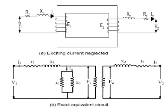
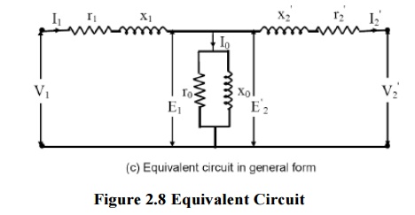
capacitances, voltages etc. In the equivalent circuit, (R1+jX1) and (R2+jX2)
are the leakage impedances of the primary and secondary windings respectively.
The primary current I1 consists of two components.One component, I1´ is the
load component and the second is no-load current Io which is composed of Ic and
Im. The current Ic is in phase with E1 and the product of these two gives core
loss. Ro represents the core loss and is called core-loss resistance. The
current Im is represented by a reactance Xo and is called
magnetizing reactance. The transformer magnetization curve is assumed linear,
since the effect of higher order harmonics can’t be represented in the
equivalent circuit.
In
transformer analysis, it is usual to transfer the secondary quantities to
primary side or primary quantities to secondary side.


Related Topics