Chapter: Design of Electrical Machines : Transformers
Output Equations and Main Dimensions- Design of Transformers
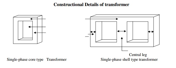
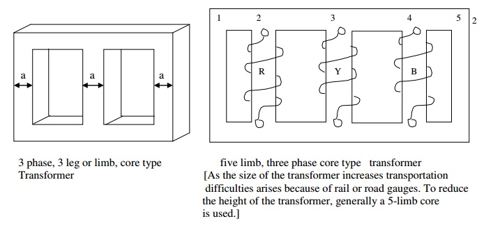
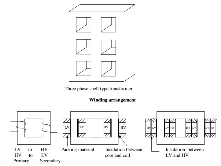
Unless otherwise specified, LV winding is always placed next to the core and HV winding over the LV winding in order to reduce the quantity of insulation used, avoid the possibility of breakdown of the space between the core and HV coil in case HV coil is provided next to the core and to control the leakage reactance. However in case of transformers where the voltage rating is less, LV and HV windings can be arranged in any manner.
SPECIFICATION
1. Output-kVA
2. Voltage-V1/V2 with or without tap changers and tapings
3. Frequency-f Hz
4. Number of phases – One or three
5. Rating – Continuous or short time
6. Cooling – Natural or forced
7. Type – Core or shell, power or distribution
8. Type of winding connection in case of 3 phase transformers – star-star, star-delta, delta-delta, delta-star with or without grounded neutral
9. Efficiency, per unit impedance, location (i.e., indoor, pole or platform mounting etc.), temperature rise etc.,
SIZE OF THE TRANSFORMER
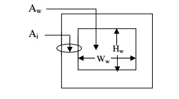
As the iron area of the leg Ai and the window area Aw = (height of the window Hw x Width of the window Ww) increases the size of the transformer also increases. The size of the transformer increases as the output of the transformer increases.
NOTE:
Nomenclature:
V1 – Applied primary voltage
V2 – Secondary terminal voltage
E1, E2 – EMF induced in the primary and secondary windings per phase in case of 3 phase
T1, T2 – Number of primary and secondary turns per phase in case of 3 phase
I1, I2 – Primary and Secondary currents per phase in case of 3 phase
a1, a2 – Cross-sectional area of the primary and secondary winding conductors
δ - Current density in the transformer conductor. Assumed to be same for both LV and HV
winding.
φm – Maximum value of the (mutual or useful) flux in weber = AiBm
Bm – Maximum value of the flux density = φm / Ai
Ai – Net iron area of the core or leg or limb = KiAg
Ki – Iron or stacking factor = 0.9 approximately
Ag – Gross area of the core

a. It is clear that V1I1 = V2I2 or volt-ampere input is equal to volt-ampere output or kVA rating of both
primary and secondary windings is same.
b. It is clear that I1T1 = I2T2 or primary mmf is equal to secondary mmf.
c. It is clear that E1/T1 = E2/T2 or volt/turn of both primary and secondary is same.
Output Equations
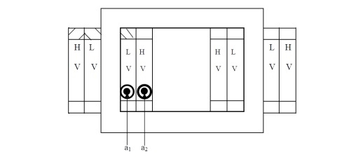
Single phase core type transformer
Rating of the transformer in kVA = V1I1 x 10-3 = E1I1 x 10-3 = 4.44 φm f T1 x I1 x 10-3----(1)

Single phase shell type transformer
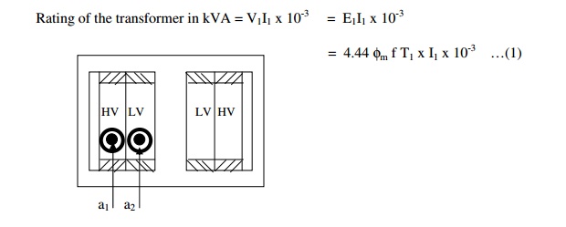
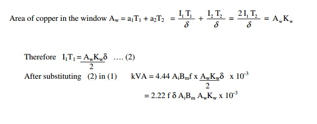
Note : Since there are two windows, it is sufficient to design one of the two windows as both the windows are symmetrical. Since the LV and HV windings are placed on the central leg, each window accommodates T1 and T2 turns of both primary and secondary windings.
Area of copper in the window
Three phase core type transformer
Rating of the transformer in kVA = V1I1 x 10-3 = E1I1 x 10-3 = 3 x 4.44 φm f T1 x I1 x 10-3…(1)
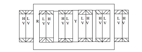
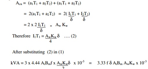
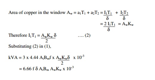
Note: Since there are two windows, it is sufficient to design one of the two windows, as both the windows are symmetrical. Since each leg carries the LV &HV windings of one phase, each window carry the LV & HV windings of two phases
Since each window carries the windings of two phases, area of copper in the window, say due to R & Y phases
Three phase shell type transformer
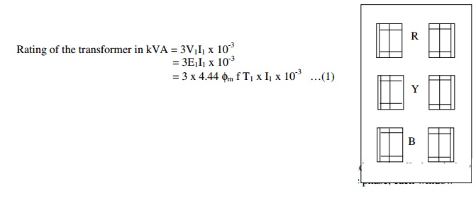
[ Note: Since there are six windows, it is sufficient to design one of the six windows, as all the windows are symmetrical. Since each central leg carries the LV and HV windings of one phase, each window carries windings of only one phase.]
Since each window carries LV and HV windings of only one phase,
Related Topics