Chapter: Design of Electrical Machines : Transformers
Volt / turn equation - Design of Transformers
Volt / turn equation
Rating of the transformer per phase
kVA / ph = V1I1 x 10-3 = E1I1
x 10-3
= 4.44 φm f T1 I1 x 10-3
The term φm is called the
magnetic loading and I1T1 is called the electric loading.
The required kVA can be obtained by selecting a higher value of φm
and a lesser of I1T1 or vice-versa.
As the magnetic loading increases, flux
density and hence the core loss increases and the
efficiency of operation decreases.
Similarly as the electric loading increases, number of turns, resistance and
hence the copper loss increases. This leads to reduced efficiency of operation.
It is clear that there is no advantage by the selection of higher values of I1T1
or φm. For an economical design they must be selected in certain
proportion. Thus in practice
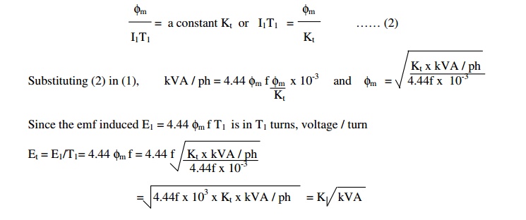
Where K = 4.44 f x 103 x
Kt is another constant and
kVA is the rated output of the transformer. The constant K depends on the type
of transformer-single or three phase, core or shell type, power or distribution
type, type of factory organization etc.,
Emperical
values of K :
( 1.0 to 1.2) for single phase shell type
1.3 for three-phase shell type (power)
(0.75 to 0.85) for single phase core type
(0.6 to 0.7) for three phase core type (power)
0.45 for three-phase core type (distribution)
Related Topics