Chapter: Design of Electrical Machines : Transformers
Design of Tank and Tubes - Transformers
Design of Tank and Tubes
Because of the losses in the transformer core and coil, the temperature of the core and coil increases. In small capacity transformers the surrounding air will be in a position to cool the transformer effectively and keeps the temperature rise well with in the permissible limits. As the capacity of the transformer increases, the losses and the temperature rise increases. In order to keep the temperature rise with in limits, air may have to be blown over the transformer. This is not advisable as the atmospheric air containing moisture, oil particles etc., may affect the insulation. To overcome the problem of atmospheric hazards, the transformer is placed in a steel tank filled with oil. The oil conducts the heat from core and coil to the tank walls. From the tank walls the heat goes dissipated to surrounding atmosphere due to radiation and convection. Further as the capacity of the transformer increases, the increased loss demands a higher dissipating area of the tank or a bigger sized tank. These calls for more space, more volume of oil and increases the cost and transportation problems. To overcome these difficulties, the dissipating area is to be increased by artificial means without increasing the size of the tank. The dissipating area can be increased by
1. fitting fins to the tank walls
2. fitting tubes to the tank and
3. using corrugated tank
4. using auxiliary radiator tanks
Since the fins are not effective in dissipating heat and corrugated tank involves constructional difficulties, they are not much used now a days. The tanks with tubes are much used in practice. Tubes in more number of rows are to be avoided as the screening of the tank and tube surfaces decreases the dissipation. Hence, when more number of tubes are to be provided, a radiator attached with the tank is considered. For much larger sizes forced cooling is adopted.
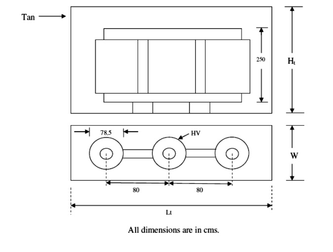
Dimensions of the Tank
The dimensions of tank depends on the type and capacity of transformer, voltage rating and electrical clearance to be provided between the transformer and tank, clearance to accommodate the connections and taps, clearance for base and oil above the transformer etc.,. These clearances can assumed to be between
(30 and 60) cm in respect of tank height (10 and 20) cm in respect of tank length and
(10 and 20) cm in respect of tank width or breadth.
Tank height Ht = [ Hw + 2Hy or 2a + clearance (30 to 60) cm ] for single and three phase core, and single phase shell type transformers.
= [3(Hw + 2Hy or 2a) + clearance (30 to 60) cm ] for a three phase shell type transformer.
Tank length Lt = [ D + Dext + clearance (10 to 20) cm ] for single phase core type transformer = [ 2D + Dext + clearance (10 to 20) cm ] for three phase core type transformer = [ 4a + 2Ww + clearance (10 to 20) cm ] for single and three phase shell type transformer.
Width or breadth of tank Wt = [ Dext + clearance (10 to 20) cm ] for all types of transformers with a circular coil.
= [ b + Ww + clearance (10 to 20) cm ] for single and three phase core type transformers having rectangular coils.
= [ b + 2Ww + clearance (10 to 20) cm ] for single and three phase shell type transformers.
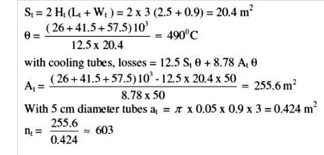
When the tank is placed on the ground, there will not be any heat dissipation from the bottom surface of the tank. Since the oil is not filled up to the brim of the tank, heat transfer from the oil to the top of the tank is less and heat dissipation from the top surface of the tank is almost negligible. Hence the effective surface area of the tank St from which heat is getting dissipated can assumed to be 2Ht (Lt + Wt) m2.
Heat goes dissipated to the atmosphere from tank by radiation and convection. It has been found by experiment that 6.0W goes radiated per m2 of plain surface per degree centigrade difference between tank and ambient air temperature and 6.5W goes dissipated by convection / m2 of plain surface / degree centigrade difference in temperature between tank wall and ambient air. Thus a total of 12.5W/m2/0C goes dissipated to the surrounding. If is the temperature rise, then at final steady temperature condition, losses responsible for temperature rise is losses dissipated or transformer losses = 12.5 St .
Number and dimensions of tubes
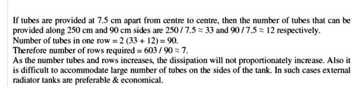
If the temperature rise of the tank wall is beyond a permissible value of about 500C, then cooling tubes are to be added to reduce the temperature rise. Tubes can be arranged on all the sides in one or more number of rows. As number of rows increases, the dissipation will not proportionally increase. Hence the number of rows of tubes are to be limited. Generally the number of rows in practice will be less than four.
With the tubes connected to the tank, dissipation due to radiation from a part of the tank surface screened by the tubes is zero. However if the radiating surface of the tube, dissipating the heat is assumed to be equal to the screened surface of the tank, then tubes can assumed to be radiating no heat. Thus the full tank surface can assumed to be dissipating the heat due to both radiation and convection & can be taken as 12.5 St watts.
Because the oil when get heated up moves up and cold oil down, circulation of oil in the tubes will be more. Obviously, this circulation of oil increases the heat dissipation. Because of this siphoning action, it has been found that the convection from the tubes increase by about 35 to 40%.
Thus if the improvement is by 35%, then the dissipation in watts from all the tubes of area At = 1.35 x 6.5At θ = 8.78 At θ..
Thus in case of a tank with tubes, at final steady temperature rise condition, Losses = 12.5 St θ + 8.78 Atθ
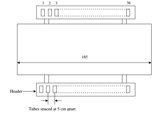
Round, rectangular or elliptical shaped tubes can be used. The mean length or height of the tubes is generally taken as about 90% of tank height.
In case of round tubes, 5 cm diameter tubes spaced at about 7.5cm (from centre to centre) are used. If dt is the diameter of the tube, then dissipating area of each tube at = πpdt x 0.9Ht. if nt is the number of tubes, then At = atnt.
Now a days rectangular tubes of different size spaced at convenient distances are being much used, as it provides a greater cooling surface for a smaller volume of oil. This is true in case of elliptical tubes also. The tubes can be arranged in any convenient way ensuring mechanical strength and aesthetic view.

Related Topics