Chapter: Design of Electrical Machines : Transformers
Resistance and Reactance of Transformer
RESISTANCE AND REACTANCE OF TRANSFORMER
Resistance:
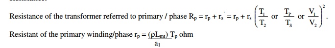
Resistivity of copper at 600C ρ= 2.1 x 10⁻⁶ ohm-cm or 2.1 x 10⁻⁸ ohm-m or 0.021 ohm/m/mm2
Mean length of turn of the primary winding Lmt P = π x mean diameter of the primary winding
Number of primary turns / phase T1 or Tp = V1ph / Et
Resistance of the secondary winding / phase rs =
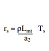
Mean length of turn of the secondary winding Lmt S = π x mean diameter of the secondary winding
Number of secondary turns / phase T2 or Ts = V2ph / Et
Reactance:
[Note: 1. Useful flux: It is the flux that links with both primary and secondary windings and is responsible in transferring the energy Electro-magnetically from primary to secondary side. The path of the useful flux is in the magnetic core.
2. Leakage flux: It is the flux that links only with the primary or secondary winding and is responsible in imparting inductance to the windings. The path of the leakage flux depends on the geometrical configuration of the coils and the neighboring iron masses.
3. Reactance:
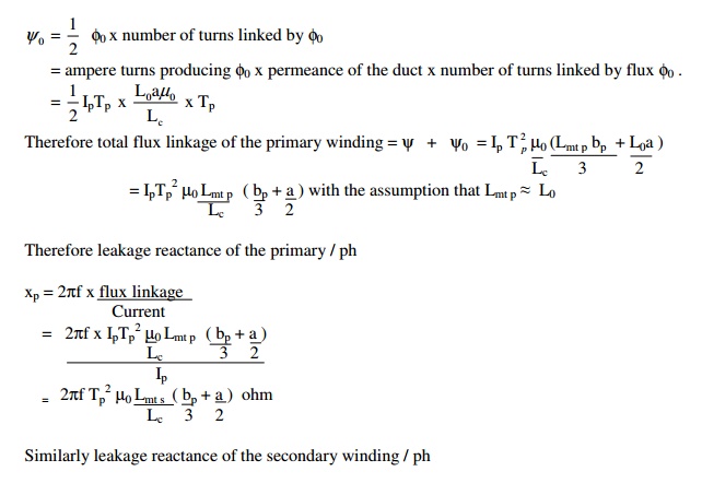
a) Leakage reactance = 2πf x inductance = 2πf x Flux linkage / current
b) Flux linkage = flux x number of turns
c) Flux =( mmf or AT) / Reluctance = AT x permeanence ∧
d) Permeanace ∧ = 1 / Reluctance = aµ0µr / l where
a = area over which the flux is established
l = length of the flux path
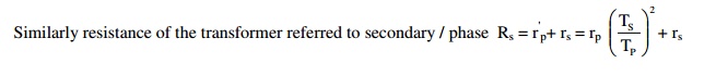
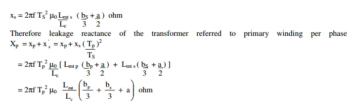
If x p and xs are the leakage reactances of the primary and secondary windings, then the total leakage reactance of the transformer referred to primary winding Xp = xp + xs = xp + xs(Tp/Ts)2
Similarly the leakage reactance of the transformer referred to secondary winding Xs = xp + xs = xp (Ts / Tp )2 + xs .
Estimation of the leakage flux or reactance is always difficult, on account of the complex geometry of the leakage flux path and great accuracy is unobtainable. A number of assumptions are to be made to get a usable approximate expression. Validity or the accuracy of the expression is checked against test data.
Expression for the leakage reactance of a core type transformer with concentric LV and HV coils of equal height or length:
Assumptions considered for the derivation:
a. Effect of magnetizing current is neglected.
b. Reluctance and effect of saturation of iron is neglected.
c. All the mmf is assumed to be used to over come the reluctance of coil height
d. Leakage flux distribution in coil and in the space between the LV and HV coils is assumed to be parallel to the leg axis.
Let,
bp and bs = Radial depth of primary and secondary windings
Tp and Ts = Number of primary and secondary turns per phase for 3 phase
Ip and Is = Primary and secondary currents per phase for 3 phase
Lmt P Lmt S = Mean length of turn of primary or secondary windings respectively
Lmt = Mean length of primary and secondary windings considered together
L0 = Circumference of the insulation portion or duct or both between LV and HV coils
Lc = Axial height or length of the both LV and HV coils
The total flux linkage of the primary or secondary winding is due to
a. Leakage flux inside the primary or secondary winding and
b. Leakage flux in between the LV and HV coils
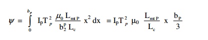
To determine the flux linkage due to the flux inside the coil, consider an elemental strip dx at a distance ‘x’ from the edge of the LV winding (say primary winding). Then the flux linkage of the primary winding, due to the flux φX in the strip.
ψX = φX x number of turns linked by φX
= ampere turns producing φX permeance of the strip x number of turns linked by φX
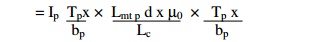
Considering the mean length of the strip is approximately equal to Lmt P .
Therefore, the total flux linkage due to the flux inside the coil
If one half of the flux φ0 in between the LV and HV windings is assumed to be linking with each windings, then the flux linkage of the primary winding due to half of the flux φ0 in between LV and HV windings,
Related Topics