Chapter: Electrical machines : Transformer
Parallel Operation of Transformers
Parallel
Operation Of Transformers
By
parallel operation we mean two or more transformers are connected to the same
supply bus bars on the primary side and to a common bus bar/load on the
secondary side. Such requirement is frequently encountered in practice. The
reasons that necessitate parallel operation are as follows.
1.
Non-availability of a single large transformer to
meet the total load requirement.
2.
The power demand might have increased over a time
necessitating augmentation of the capacity. More transformers connected in
parallel will then be pressed into service.
3.
To ensure improved reliability. Even if one of the
transformers gets into a fault or is taken out for maintenance/repair the load
can continued to be serviced.
4. To reduce
the spare capacity. If many smaller size transformers are used one machine can
be used as spare. If only one large machine is feeding the load, a spare of
similar rating has to be available. The problem of spares becomes more acute
with fewer machines in service at a location.
5.
When transportation problems limit installation of
large transformers at site, it may be easier to transport smaller ones to site
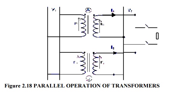
and work them in parallel. Fig. 37 shows the physical arrangement of two single
phase transformers working in parallel on the primary side. Transformer A and
Transformer B are connected to input voltage bus bars. After ascertaining the
polarities they are connected to output/load bus bars. Certain conditions have
to be met before two or more transformers are connected in parallel and share a
common load satisfactorily. They are,
1.
The voltage ratio must be the same.
2.
The per unit impedance of each machine on its own
base must be the same.
3.
The polarity must be the same, so that there is no
circulating current between the transformers.
4.
The phase sequence must be the same and no phase
difference must exist between the voltages of the two transformers.
Where,
V1=Load
bus voltage
V2=Supply
voltage
These
conditions are examined first with reference to single phase transformers and
then the three phase cases are discussed. Same voltage ratio generally the
turns ratio and voltage ratio are taken to be the same. If the ratio is large
there can be considerable error in the voltages even if the turns ratios are
the same. When the primaries are connected to same bus bars, if the secondaries
do not show the same voltage, paralleling them would result in a circulating
current between the secondaries. Reflected circulating current will be there on
the primary side also. Thus even without connecting a load considerable current
can be drawn by the transformers and they produce copper losses. In two
identical transformers with percentage impedance of 5 percent, a no-load
voltage difference of one percent will result in a circulating current of 10
percent of full load current. This circulating current gets added to the load
current when the load is connected resulting in unequal sharing of the load. In
such cases the combined full load of the two transformers can never be met
without one transformer getting overloaded.
Per unit
impedance Transformers of different ratings may be required to operate in
parallel. If they have to share the total load in proportion to their ratings
the larger machine has to draw more current. The voltage drop across each
machine has to be the same by virtue of their connection at the input and the
output ends. Thus the larger machines have smaller impedance and smaller
machines must have larger ohmic impedance. Thus the impedances must be in the
inverse ratios of the ratings. As the voltage drops must be the same the per
unit impedance of each transformer on its own base, must be equal. In addition
if active and reactive powers arerequired to be shared in proportion to the ratings
the impedance angles also must be the same. Thus we have the requirement that
per unit resistance and per unit reactance of both the transformers must be the
same for proper load sharing. Polarity of connection The polarity of connection
in the case of single phase transformers can be either same or opposite. Inside
the loop formed by the two secondaries the resulting voltage must be zero.
If wrong
polarity is chosen the two voltages get added and short circuit results. In the
case of polyphase banks it is possible to have permanent phase error between
the phases with substantial circulating current. Such transformer banks must
not be connected in parallel. The turn’s ratios in such groups can be adjusted
to give very close voltage ratios but phase errors cannot be compensated. Phase
error of 0.6 degree gives rise to one percent difference in voltage. Hence poly
phase transformers belonging to the same vector group alone must be taken for
paralleling. Transformers having −30degree angle can be paralleled to that
having +30 angle by reversing the phase sequence of both primary and secondary
terminals of one of the transformers.
This way
one can overcome the problem of the phase angle error. Phase sequence the phase
sequence of operation becomes relevant only in the case of poly phase systems.
The poly phase banks belonging to same vector group can be connected in
parallel. A transformer with +30◦ phase angle however can be paralleled with
the one with −30∙ phase angle; the phase sequence is reversed for one of them
both at primary and secondary terminals. If the phase sequences are not the
same then the two transformers cannot be connected in parallel even if they
belong to same vector group.
The phase
sequence can be found out by the use of a phase sequence indicator. Performance
of two or more single phase transformers working in parallel can be computed
using their equivalent circuit. In the case of poly phase banks also the
approach is identical and the single phase equivalent circuit of the same can
be used. Basically two cases arise in these problems. Case A: when the voltage
ratio of the two transformers is the same and Case B: when the voltage ratios
are not the same. These are discussed now in sequence.
Related Topics