Chapter: Electrical machines : Transformer
Transformer Tests
Transformer Tests
1 .Open-circuit or no-load test
2. Short circuit or impedance test
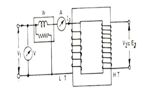
1. Open-circuit or No-load Test.
In this test secondary (usually high voltage) winding is left open, all metering instruments (ammeter, voltmeter and wattmeter) are connected on primary side and normal rated voltage is applied to the primary (low voltage) winding, as illustrated below
Iron loss = Input power on no-load
W0 watts (wattmeter reading) No-load current = 0 amperes (ammeter reading) Angle of lag, = /Io Ie = and Im = √o - Caution: Since no load current I0 is very small, therefore, pressure coils of watt meter and the volt meter should be connected such that the current taken by them should not flow through the current taken by them should not flow through the current coil of the watt meter.
V0 = Rated Voltage
Wo = Input power
I0 = Input current = no oad current
Im = I0sinϕ0
Ic = I0cos ϕ0
cos ϕ0 = No load power factor
Hence power input can be written as,
Wo = V0 I0 cos ϕ0
W0 = Pi = Iron losses
W0 = V0I0 cos ϕ0
cos ϕ0 = W0 / V0I0 = no load power factor
Ro = V0/Ic Ω
X0 = V0 /Im
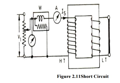
2. Short-circuit or Impedance Test.
This test is performed to determine the full-load copper loss and equivalent resistance and reactance referred to secondary side. In this test, the terminals of the secondary (usually the low voltage) winding are short circuited, all meters (ammeter, voltmeter and wattmeter) are connected on primary side and a low voltage, usually 5 to 10 % of normal rated primary voltage at normal frequency is applied to the primary, as shown in fig below.
The applied voltage to the primary, say Vs’ is gradually increased till the ammeter A indicates the full load current of the side in which it is connected. The reading Ws of the wattmeter gives total copper loss (iron losses being negligible due to very low applied voltage resulting in very small flux linking with the core) at full load. Le the ammeter reading be Is.
Equivalent impedence referred to primary= Commercial Efficiency and All day Efficiency (a) Commercial Efficiency. Commercial efficiency is defined as the ratio of power output to power input in kilowatts.(b) All-day Efficiency. The all day efficiency is defined as the ratio of output in kwh to the input in kwh during the whole day. Transformers used for distribution are connected for the whole day to the line but loaded intermittently. Thus the core losses occur for the whole day but copper losses occur only when the transformer is delivering the load current. Hence if the transformer is not used to supply the load current for the whole day all day efficiency will be less than commercial efficiency. The efficiency (commercial efficiency) will be maximum when variable losses (copper losses) are equal to constant losses (iron or core losses).sign is for inductive load and sign is for capacitive load Transformer efficiency, Where x is the ratio of secondary current I2 and rated full load secondary current.
Wsc = (Pcu) F.L. = full Load copper loss
Wsc = VscIsc cosϕsc
cosϕsc = VscIsc / Wsc
Wsc = I2sc R1e = Copper loss
Z1e = Vsc /Isc = Root(R21e+X21e)
X1e = Root(Z21e – R21e)
Related Topics