Chapter: Electrical machines : Transformer
Solved Problems - Transformer - Electrical machines
SOLVED
PROBLEMS
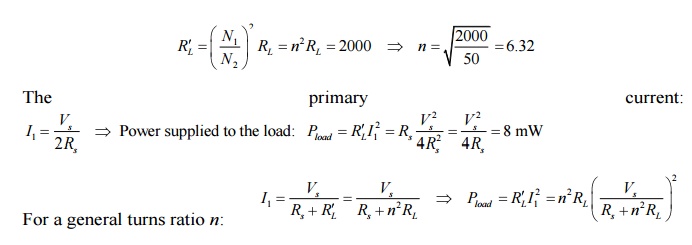
Example
1:
A source
which can be represented by a voltage source of 8 V rms in series with an
internal resistance of 2 kΩ is connected to a 50-Ω load resistance through an
ideal transformer. Calculate the value of turns ratio for which maximum power
is supplied to the load and the corresponding load power? Using MATLAB, plot
the the power in milliwatts supplied to the load as a function of the
transformer ratio, covering ratios from 1.0 to 10.0.
Solution:
For
maximum power transfer, the load resistance (referred to the primary) must be
equal to the source resistance.
Example 2
A 460-V:2400-V
transformer has a series leakage reactance of 37.2 Ω as referred to the
high-voltage side. A load connected to the low-voltage side is observed to be
absorbing 25 kW, unity power factor, and the voltage is measured to be 450 V.
Calculate the corresponding voltage and power factor as measured at the
high-voltage terminals.
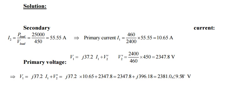
Power factor at primary
terminals: cos(9.58 ) = 0.9861 lagging
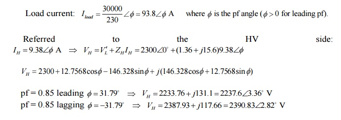
Example 3:
The
resistances and leakage reactances of a 30-kVA, 60-Hz, 2400-V:240-V distribution
transformer are
R1
= 0.68 Ω
R2
= 0.0068 Ω
Xl1
= 7.8 Ω
Xl2
= 0.0780 Ω
where
subscript 1 denotes the 2400-V winding and subscript 2 denotes the 240-V
winding. Each quantity is referred to its own side of the transformer.
a.
Draw the equivalent circuit referred to (i) the
high- and (ii) the low-voltage sides. Label the impedances numerically.
b.
Consider the transformer to deliver its rated kVA
to a load on the low-voltage side with 230 V across the load. (i) Find the
high-side terminal voltage for a load power factor of 0.85 lagging. (ii) Find
the high-side terminal voltage for a load power factor of 0.85 leading.
c.
Consider a rated-kVA load connected at the
low-voltage terminals operating at 240V. Use MATLAB to plot the high-side
terminal voltage as a function of the power-factor angle as the load power
factor varies from 0.6 leading through unity power factor to 0.6 pf lagging.

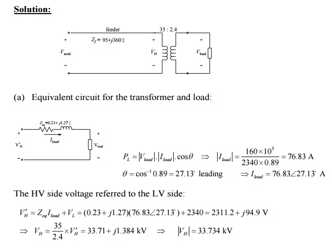
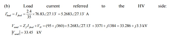
Example 4:
A
single-phase load is supplied through a 35-kV feeder whose impedance is 95 + j360 Ω and a 35-kV:2400-V transformer
whose equivalent impedance is (0.23 + j1.27)
Ω referred to its low-voltage side. The load is 160 kW at 0.89 leading power
factor and 2340 V.
a.
Compute the voltage at the high-voltage terminals
of the transformer.
b.
Compute the voltage at the sending end of the feeder.
Compute
the power and reactive power input at the sending end of the feeder.
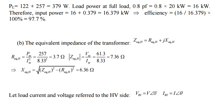
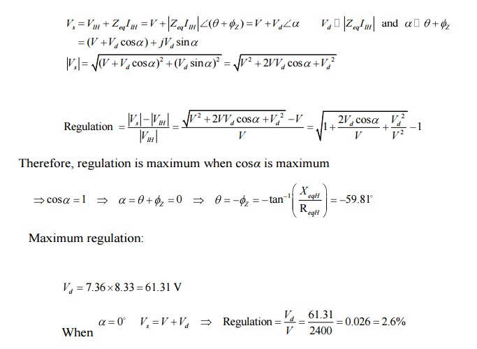
Example 5:
The
following data were obtained for a 20-kVA, 60-Hz, 2400:240-V distribution
transformer tested at 60 Hz:
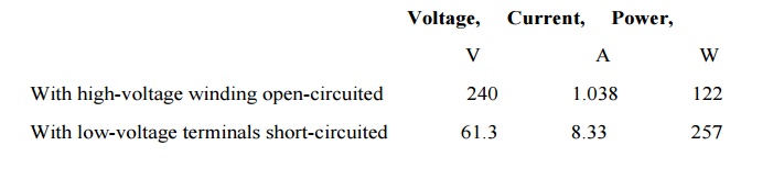
a.
Compute the efficiency at full-load current and the
rated terminal voltage at 0.8 power factor.
b.
Assume that the load power factor is varied while
the load current and secondary terminal voltage are held constant. Use a phasor
diagram to determine the load power factor for which the regulation is
greatest. What is this regulation?
Solution:
(a)
Rated current on the HV side = 20 kVA / 2400 = 8.33
A. Therefore, total power loss at full load current:
Example 6:
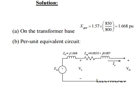
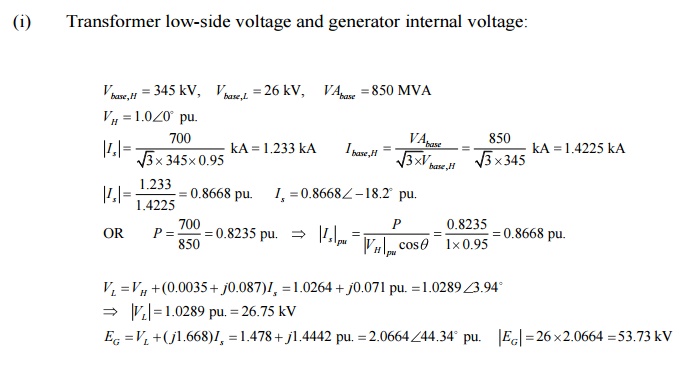
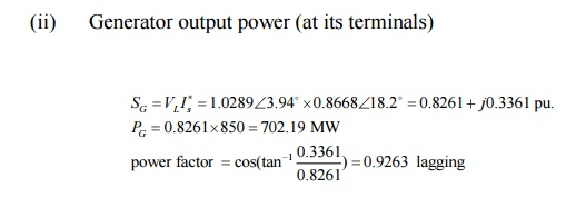
A
three-phase generator step-up transformer is rated 26-kV:345-kV, 850 MVA and
has a series impedance of 0.0035 + j0.087 per unit on this base. It is
connected to a 26-kV, 800-MVA generator, which can be represented as a voltage
source in series with a reactance of j1.57
per unit on the generator base.
(a)
Convert the per unit generator reactance to the
step-up transformer base.
(b)
The unit is supplying 700 MW at 345 kV and 0.95
power factor lagging to the system at the transformer high-voltage terminals.
(i)
Calculate the transformer low-side voltage and the
generator internal voltage behind its reactance in kV.
(ii)
Find the generator output power in MW and the power
factor.
Solution:
Related Topics