Double slit as coherent sources | Interference - Young’s double slit experiment | 12th Physics : UNIT 7 : Wave Optics
Chapter: 12th Physics : UNIT 7 : Wave Optics
Young’s double slit experiment
Double slit as coherent sources
Double slit uses the principle of wavefront division. Two slits S1 and S2 illuminated by a single monochromatic source S act as a set of coherent sources. The waves from these two coherent sources travel in the same medium and superpose. The constructive and destructive interference are shown in Figure 6.57(a).The crests of the waves are shown by thick continuous lines and troughs are shown by broken lines in Figure 6.57(b).
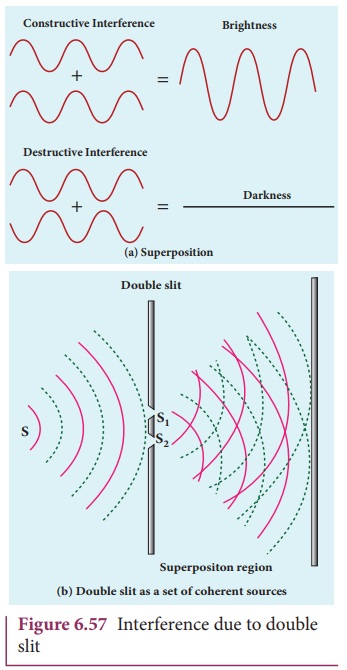
At points where the crest of one wave meets the crest of the other wave or the trough of one wave meets the trough of the other wave, the waves are in-phase. Hence, the displacement is maximum and these points appear bright. This type of interference is said to be constructive interference.
At points where the crest of one wave meets the trough of the other wave and vice versa, the waves are out-of-phase. Hence, the displacement is minimum and these points appear dark. This type of interference is said to be destructive interference.
On a screen the intensity of light will be alternatively maximum and minimum i.e. bright and dark bands which are referred as interference fringes.
Young’s double slit experiment
Thomas Young, a British Physicist used an opaque screen with two small openings called double slit S1 and S2 kept equidistance from a source S as shown in Figure 6.62. The width of each slit is about 0.03 mm and they are separated by a distance of about 0.3 mm. As S1 and S2 are equidistant from S, the light waves from S reach S1 and S2 in-phase. So, S1 and S2 act as coherent sources which are the requirement of obtaining interference pattern.
Experimental setup
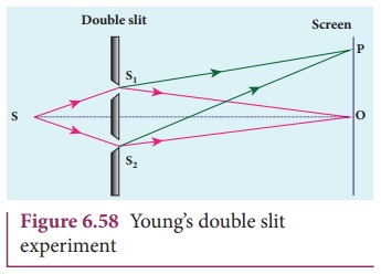
Wavefronts from S1 and S2 spread out and overlapping takes place to the right side of double slit. When a screen is placed at a distance of about 1 meter from the slits, alternate bright and dark fringes which are equally spaced appear on the screen. These are called interference fringes or bands. Using an eyepiece the fringes can be seen directly. At the center point O on the screen, waves from S1 and S2 travel equal distances and arrive in-phase as shown in Figure 6.58. These two waves constructively interfere and bright fringe is observed at O. This is called central bright fringe. The fringes disappear and there is uniform illumination on the screen when one of the slits is covered. This shows clearly that the bands are due to interference.
Equation for path difference
The schematic diagram of the experimental set up is shown in Figure 6.59. The Let d be the distance between the double slits S1 and S2 which act as coherent sources of wavelength λ. A screen is placed parallel to the double slit at a distance D from it. The mid-point of S1 and S2 is C and the mid-point of the screen O is equidistant from S1 and S2. P is any point at a distance y from O. The waves from S1 and S2 meet at P either in-phase or out-of-phase depending upon the path difference between the two waves.
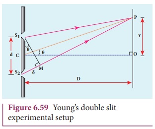
The path difference δ between the light waves from S1 and S2 to the point P is, δ = S2P – S1P
A perpendicular is dropped from the point S1 to the line S2P at M to find the path difference more precisely.
δ = S2P – MP = S2M …….(6.137)

The angular position of the point P from C is θ. ∠OCP = θ.
From the geometry, the angles ∠OCP and ∠S2S1M are equal.
∠OCP = ∠S2S1M = θ.
In right angle triangle ∆S1S2M, the path difference, S2M = d sin θ

If the angle θ is small, sin θ ≈ tan θ ≈ θ
From the right angle triangle ∆OCP, tanθ = y/D

Based on the condition on the path difference, the point P may have a bright or dark fringe.
Condition for bright fringe (or) maxima
The condition for the constructive interference or the point P to be have a bright fringe is,
Path difference, δ = nλ
where, n = 0, 1, 2, . . .
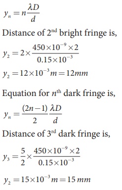
∴ d y/D = nλ
This is the condition for the point P to be a bright fringe. The distance is the distance of the nth bright fringe from the point O.
Condition for dark fringe (or) minima
The condition for the destructive interference or the point P to be have a dark fringe is,
Path difference, δ = (2n −1) λ/2
where, n = 1, 2, 3 . . .
∴ d y/D = (2n −1) λ/2
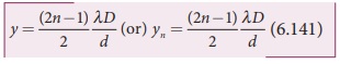
This is the condition for the point P to be a dark fringe. The distance yn is the distance of the nth dark fringe from the point O.
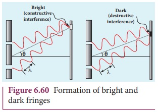
The formation of bright and dark fringes is shown in Figure 6.60.
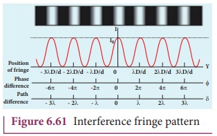
This shows that on the screen, alternate bright and dark bands are seen on either side of the central bright fringe. The central bright is referred as 0th bright followed by 1st dark and 1st bright and then 2nd dark and 2nd bright and so on, on either side of O successively as shown in Figure 6.61.
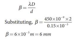
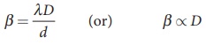
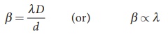
Equation for bandwidth
The bandwidth (β) is defined as the distance between any two consecutive bright or dark fringes.
The distance between (n+1)th and nth consecutive bright fringes from O is given by,
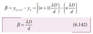
Similarly, the distance between (n+1)th and n consecutive dark fringes from O is given by,
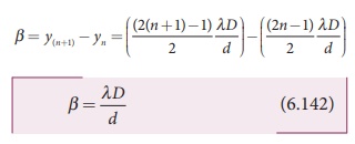
Equations (6.142) show that the bright and dark fringes are of same width equally spaced on either side of central bright fringe.
Conditions for obtaining clear and broad interference bands
(i) The screen should be as far away from the source as possible.
(ii) The wavelength of light used must be larger.
(iii) The two coherent sources (here S1 and S2) must be as close as possible.
EXAMPLE 6.28
In Young’s double slit experiment, the two slits are 0.15 mm apart. The light source has a wavelength of 450 nm. The screen is 2 m away from the slits.
(i) Find the distance of the second bright fringe and also third dark fringe from the central maximum.
(ii) Find the fringe width.
(iii) How will the fringe pattern change if the screen is moved away from the slits?
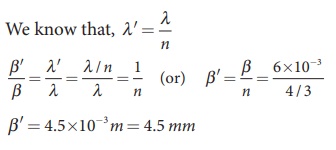
(iv) What will happen to the fringe width if the whole setup is immersed in water of refractive index 4/3.
Solution
d = 0.15 mm = 0.15× 10⁻³ m; D = 2 m;
λ = 450 nm = 450 × 10-9 m; n = 4/3
(i) Equation for nth bright fringe is,
(ii) Equation for fringe width is,
(iii) The fringe width will increase as D is increased,
(iv) The fringe width will decrease as the setup is immersed in water of refractive index 4/3
The wavelength will decrease refractive index n times.
Hence, β ∝ λ and β’ ∝ λ’
Related Topics