Optics | Physics - Diffraction | 12th Physics : UNIT 7 : Wave Optics
Chapter: 12th Physics : UNIT 7 : Wave Optics
Diffraction
DIFFRACTION
Diffraction is a general characteristic
of all types of waves, be it sound wave, light wave, water wave etc. Diffraction
is bending of waves around sharp edges into the geometrically shadowed
region. This is a violation to the rectilinear propagation of light, we
have studied in ray optics, which says light should travel in straight line in
a medium without bending. But, the diffraction is prominent only when the size
of the obstacle is comparable to the wavelength of light. This is the reason
why sound waves get diffracted prominently by obstacles like doors, windows,
buildings etc. The wavelength of sound wave is large and comparable to the
geometry of these obstacles. But the diffraction in light is more pronounced
when the obstacle size is of the order of wavelength of light.
1. Fresnel and Fraunhofer diffractions
Based on the type of wavefront which
undergoes diffraction, the diffraction could be classified as Fresnel and
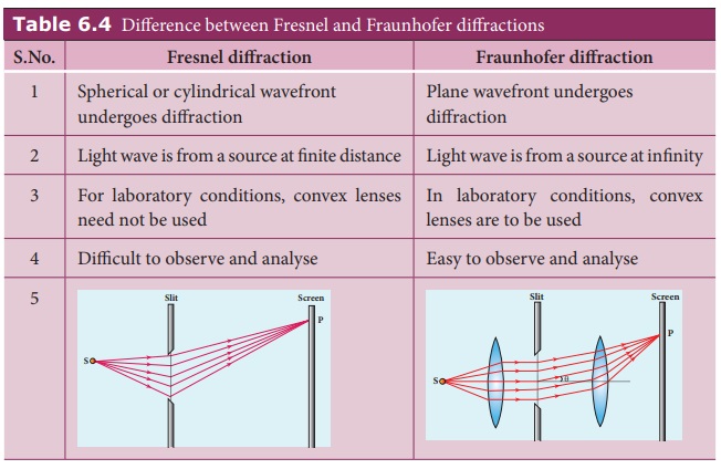
Fraunhofer diffractions. The differences between Fresnel and Fraunhofer
diffractions are shown in Table 6.4.
As Fraunhofer diffraction is easy to observe and
analyse, let us take it up for further discussions.
Table 6.4 Difference between Fresnel and
Fraunhofer diffractions
Fresnel
diffraction
• Spherical or cylindrical wavefront undergoes
diffraction
• Light wave is from a source at finite distance
• For laboratory conditions, convex lenses need
not be used
• Difficult to observe and analyse
Fraunhofer
diffraction
• Plane wavefront undergoes diffraction
• Light wave is from a source at infinity
• In laboratory conditions, convex lenses are to
be used
• Easy to observe and analyse
2. Diffraction at single slit
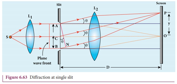
Let a parallel beam of light fall
normally on a single slit AB of width a as shown in Figure 6.63. The diffracted
beam falls on a screen kept at a distance. The center of the slit is C. A straight line through C perpendicular to the plane of slit meets
the center of the screen at O. We
would like to find the intensity at any point P on the screen. The lines joining P to the different points on the slit can be treated as parallel
lines, making an angle θ with the
normal CO.
All the waves start parallel to each
other from different points of the slit and interfere at point P and other points to give the resultant
intensities. The point P is in the
geometrically shadowed region, up to which the central maximum is spread due to
diffraction as shown Figure 6.63. We need to give the condition for the point P to be of various minima.
The basic idea is to divide the slit
into much smaller even number of parts. Then, add their contributions at P with the proper path difference to
show that destructive interference takes place at that point to make it
minimum. To explain maximum, the slit is divided into odd number of parts.
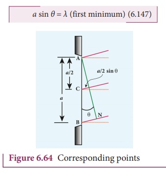
Condition for P to be first minimum
Let us divide the slit AB into two half ’s AC and CB. Now the width
of AC is (a/2). We have different points on the slit which are separated by
the same width (here a/2) called corresponding points as shown in Figure
6.64.
The path difference of light waves
from different corresponding points meeting at point P and interfere
destructively to make it first minimum. The path difference δ between waves from these corresponding
points is, δ = a/2 sinθ
The condition for P to be first
minimum, a/2 sinθ = λ/2
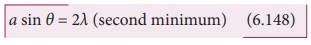
Condition for P to be second minimum
Let us divide the slit AB into four equal parts. Now, the width
of each part is a/4. We have several
corresponding points on the slit which are separated by the same width a/4. The path difference δ between waves from these corresponding
points is, δ = a/4 sinθ.
The condition for P to be second minimum, a/4 sinθ = λ/2
a sin θ = 2λ (second minimum) (6.148)
Condition for P to be third order minimum
The same way the slit is divided in
to six equal parts to explain the condition for P to be third minimum is, a/6
sinθ = λ/2

a sin θ = 3λ (third minimum) (6.149)
Condition for P to be nthorder minimum
Dividing the slit into 2n number of (even number of) equal parts
makes the light produced by one of the corresponding points to be cancelled by
its counterpart. Thus, the condition for nth
order minimum is a/2n sinθ = λ/2
a sin θ = nλ (nth minimum) (6.150)

Condition for maxima
For points of maxima, the slit is to
be divided in to odd number of equal parts so that one part remains
un-cancelled making the point P appear
bright.
The condition for first maximum is,
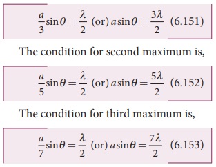
In the same way, condition for nth
maximum is,
where, n = 0, 1, 2, 3, . . . , is the order of diffraction maximum.
The central maximum is called 0th
order maximum. The points of the maximum intensity lie nearly midway between
the successive minima.
Here, sinθ gives the angular spread
of the diffraction. The position of the minimum or maximum in terms of y may be
expressed by replacing sinθ approximated by tanθ, as θ is small, sinθ = tanθ y/D
Where, y is the position of the
minimum from the center of the screen and D is the distance between single slit
and the screen.
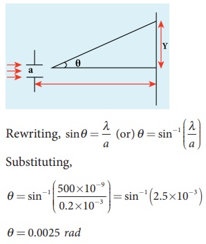
EXAMPLE 6.31
Light of wavelength 500 nm passes
through a slit of 0.2 mm wide. The diffraction pattern is formed on a screen 60
cm away. Determine the,
(i) angular spread of central maximum
(ii) the distance between the
central maximum and the second minimum.
Solution
λ = 500 nm = 500×10-9 m; a = 0.2 mm = 0.2×10⁻³ m; D = 60 cm = 60×10-2 m
(i) Equation for diffraction minimum
is, a sin θ = nλ
The central maximum is spread up to
the first minimum. Hence, n = 1
(ii) To find the value of y1 for central maximum, which
is spread up to first minimum with (n =
1) is, a sin θ = λ
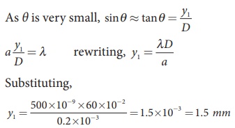
To find the value of y2
for second minimum with (n = 2) is, a
sin θ = 2λ
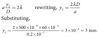
The distance between the central
maximum and second minimum is, y2
– y1
y2 – y1 = 3
mm – 1.5 mm = 1.5 mm
Note: The above calculation shows that in
the diffraction pattern caused by single slit, the width of each maximum is
equal with central maximum as the double that of others. But the bright and dark
fringes are not of equal width.
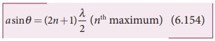
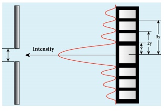
EXAMPLE 6.32
A monochromatic light of wavelength
5000 Å passes through a single slit producing diffraction pattern for the
central maximum as shown in the figure. Determine the width of the slit.
Solution
λ = 5000 Å = 5000×10-10 m;
sin 30º = 0.5; n = 1; a =?
Equation for diffraction minimum is,
asin θ = nλ
The central maximum is spread up to
the first minimum. Hence, n = 1
Rewriting, a = λ / Sinθ
Substituting, a = 5000×10−10 / 0.5
a = 1×10⁻⁶ m = 0.001×10⁻³m = 0.001mm
3. Discussion on first minimum
Let us consider the condition for
first minimum with (n = 1). a sin θ = λ
The first minimum has an angular
spread of, sinθ = λ/a
Now, we have special cases to
discuss on the above condition.
(i) When a < λ, the diffraction is not possible, because sinθ can never be greater than 1.
(ii) When a ≥ λ, the diffraction is possible.
◗ For a =
λ, sinθ = 1 i.e, θ = 90º. That means the first minimum is at 90º. Hence, the
central maximum spreads fully in to the geometrically shadowed region leading
to bending of the diffracted light to 90º.
◗ For a >> λ, sinθ << 1 i.e, the first minimum will fall within the width of
the slit itself. The diffraction will not be noticed at all.
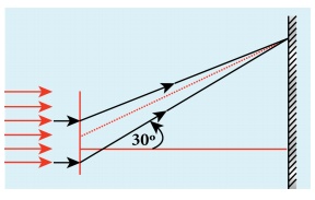
(iii) When a > λ and also
comparable, say a = 2λ, sinθ = λ/a = λ/2λ = 1/2; then θ = 30º. These
are practical cases where diffraction could be observed effectively.
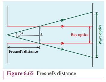
4. Fresnel’s distance
Fresnel’s distance is the distance up to which the ray optics is
valid in terms of rectilinear propagation of light. As there is bending of light in diffraction, the rectilinear
propagation of light is violated. But, this bending is not significant till the
diffracted ray crosses the central maximum at a distance z as shown in Figure 6.65. Hence, Fresnel’s distance is the distance upto which ray optics is obeyed and
beyond which ray optics is not obeyed but, wave optics becomes significant.
From the diffraction equation for
first minimum, sinθ =
λ/a; θ = λ/a
From the definition of Fresnel’s
distance, sin2θ = a/z; 2θ =
a/z
Equating the above two equation
gives, λ/a=a/2z
After rearranging, we get Fresnel’s
distance z as,

EXAMPLE 6.33
Calculate the distance for which ray
optics is good approximation for an aperture of 5 mm and wavelength 500 nm.
Solution
a = 5 mm = 5 × 10⁻³ m;
λ = 500nm = 500×10−9 m;
z = ?
Equation for Fresnel’s distance, z = a2/2λ
Substituting,
z = [5 × 10⁻³]2 / 2×500×10−9
z = 25 m
5. Difference between interference and diffraction
It is very difficult to distinguish
between interference and diffraction as they both exhibit the wave nature of
light. In both the phenomena the light reaches the geometrically shadowed regions
and also interferes to produce maximaand minima. Nevertheless, based on the appearance,
the differences are given in Table 6.5.
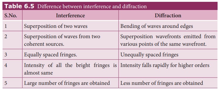
Table 6.5 Difference between interference and diffraction
6. Diffraction in grating
Grating has multiple slits with
equal widths of size comparable to the wavelength of diffracting light. Grating
is a plane sheet of transparent material on which opaque rulings are made with
a fine diamond pointer. The modern commercial grating contains about 6000 lines
per centimetre. The rulings act as obstacles having a definite width b and the transparent space between the
rulings act as slit of width a. The combined width of a ruling and a slit
is called grating element (e = a
+ b). Points on successive slits separated by a distance equal to the grating
element are called corresponding points.
Interference
• Superposition of two waves
• Superposition of waves from two coherent
sources.
• Equally spaced fringes.
• Intensity of all the bright fringes is almost
same
• Large number of fringes are obtained
Diffraction
• Bending of waves around edges
• Superposition wavefronts emitted from various
points of the same wavefront.
• Unequally spaced fringes
• Intensity falls rapidly for higher orders
• Less number of fringes are obtained
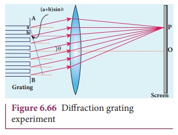
A plane transmission grating is represented
by AB in Figure 6.66. Let a plane
wavefront of monochromatic light with wave length λ be incident normally on the grating. As the slits size is
comparable to that of wavelength, the incident light diffracts at the grating.
A diffraction pattern is obtained on
the screen when the diffracted waves are focused on a screen using a convex
lens. Let us consider a point P at an
angle θ with the normal drawn from
the center of the grating to the screen. The path difference δ between the diffracted waves from one
pair of corresponding points is,

δ = (a + b) sinθ (6.156)
This path difference is the same for
any pair of corresponding points. The point P
will be bright, when

δ = m λ where m = 0, 1, 2, 3 (6.157)
Combining the above two equations,
we get,

(a
+ b) sinθ = m λ (6.158)
Here, m is called order of
diffraction.
Condition for zero order maximum, m = 0
For (a + b) sinθ = 0, the position, θ = 0. sinθ = 0 and m = 0. This is
called zero order diffraction or central maximum.
Condition for first order maximum, m = 1
If (a + b) sinθ1 = λ, the diffracted light meet at an angle θ1 to the incident direction and the first order maximum
is obtained.
Condition for second order maximum, m = 2
Similarly, (a + b) sinθ2 = 2λ forms the second order maximum at the angular position θ2.
Condition for higher order maximum
On either side of central maxima
different higher orders of diffraction maxima are formed at different angular
positions.
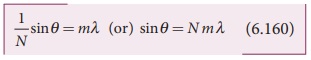
If we take,

Then, N gives the number of grating elements or rulings drawn per unit
width of the grating. Normally, this number N
is specified on the grating itself. Now, the equation becomes,
The students should remember that in
a single slit experiment the formula, a sinθ = nλ is condition for minimum with
n as order of minimum. But, the formula in diffraction grating, sinθ = Nmλ is condition for maxima with m as
the order of diffraction.
EXAMPLE 6.34
A diffraction grating consisting of
4000 slits per centimeter is illuminated with a monochromatic light that
produces the second order diffraction at an angle of 30°. What is the
wavelength of the light used?
Solution
Number of lines per cm = 4000; m = 2;
θ = 30°; λ = ?
Number of lines per unit length,
N = 4000 / 1×10−2 = 4×10⁵
Equation for diffraction maximum in grating
is, sinθ = Nmλ
Rewriting, λ = sinθ / Nm
Substituting,
λ = sin 30º / 4×105×2
= 0.5 / 4×105×2
= 1 / [2×4×105 ×2] = 1 /
[16×105]
λ = 6250×10−10 m = 6250 Ao
EXAMPLE 6.35
A monochromatic light of wavelength of
500 nm strikes a grating and produces fourth order bright line at an angle of
30°. Find the number of slits per centimeter.
Solution
λ = 500 nm = 500×10-9 m; m = 4;
θ = 30°; number of lines per cm = ?
Equation for diffraction maximum in
grating is, sin θ = Nm λ
Rewriting, N = sinθ / mλ
Substituting,
N = 0.5 / 4×500×10−9 = 1 /
2×4×500×10−9
N = 2.5×10⁵ lines per
meter
number of lines per centimeter = 2.5×105 ×10−2 = 2500 lines per
centimetre
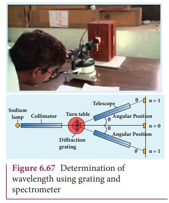
7. Experiment to determine the wavelength of monochromatic light
The wavelength of a spectral line can
be very accurately determined with the help of a diffraction grating and a spectrometer.
Initially all the preliminary adjustments of the spectrometer are made. The
slit of collimator is illuminated by a monochromatic light, whose wavelength is
to be determined. The telescope is brought in line with collimator to view the
image of the slit. The given plane transmission grating is then mounted on the
prism table with its plane perpendicular to the incident beam of light coming
from the collimator. The telescope is turned to one side until the first order
diffraction image of the slit coincides with the vertical cross wire of the eye
piece. The reading of the position of the telescope is noted.
Similarly the first order diffraction
image on the other side is made to coincide with the vertical cross wire and
corresponding reading is noted. The difference between two positions gives 2θ. Half of its value gives θ, the diffraction angle for first order
maximum as shown in Figure 6.67. The wavelength of light is calculated from the
equation,

Here, N is the number of rulings per metre in the grating and m is the
order of the diffraction image.
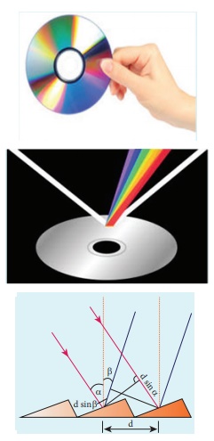
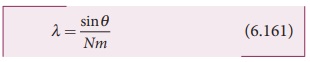
You would have noticed the colourful
appearance of the compact disc. On the read/writable side which is polished,
there are many narrow circular tracks with widths comparable to the wavelength
of visible light. Hence, the diffraction takes place after reflection for
incident white light to give colourful appearance. The tracks act as reflecting
grating.
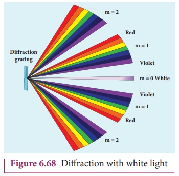
8. Determination of wavelength of different colours
When white light is used, the diffraction
pattern consists of a white central maximum and on both sides continuous
coloured diffraction patters are formed. The central maximum is white as all
the colours meet here constructively with no path difference. As θ increases, the path difference, (a+b)sinθ, passes through condition for maxima
of diffraction of different orders for all colours from violet to red. It
produces a spectrum of diffraction pattern from violet to red on either side of
central maximum as shown in Figure 6.68. By measuring the angle at which these
colours appear for various orders of diffraction, the wavelength of different
colours could be calculated using the formula,
Here, N is the number of rulings per
metre in the grating and m is the order of the diffraction image.
9. Resolution
The effect of diffraction has an
adverse impact in the image formation by the optical instruments such as
microscope and telescope. For a single rectangular slit, the half angle θ subtended by the spread of central
maximum (or position of first minimum) is given by the relation,
a sinθ = λ (6.162)

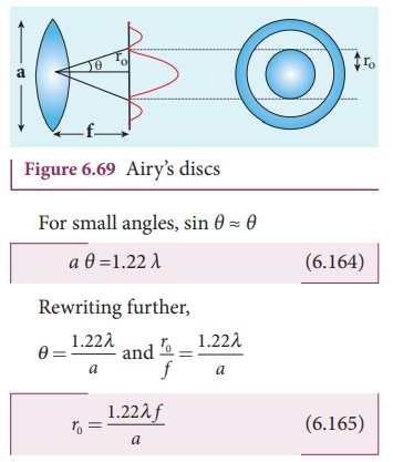
Similar to a rectangular slit, when
a circular aperture or opening (like a lens or the iris of our eye) forms an
image of a point object, the image formed will not be a point but a diffraction
pattern of concentric circles that becomes fainter while moving away from the
center as shown in Figure 6.69. These are known as Airy’s discs. The circle of
central maximum has the half angular spread given by the equation,
a sinθ = 1.22 λ (6.163)

Here, the numerical value 1.22 comes
for central maximum formed by circular apertures. This involves higher level
mathematics which is avoided in this discussion.
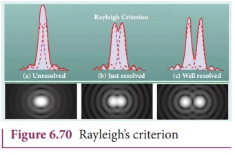
When two point sources close to each another form image on the screen, the diffraction pattern of one point source can overlap with another and produce a blurred image as shown in Figure 6.70(a). To obtain a good image of the two sources, the two point sources must be resolved i.e., the point sources must be imaged in such a way that their images are sufficiently far apart that their diffraction patterns do not overlap. According to Rayleigh’s criterion, for two point objects to be just resolved, the minimum distance between their diffraction images must be in such a way that the central maximum of one coincides with the first minimum of the other and vice versa as shown in Figure 6.70(b). Such an image is said to be just resolved image of the object. The Rayleigh’s criterion is said to be limit of resolution.
According to Rayleigh’s criterion
the two point sources are said to be just resolved when the distance between
the two maxima is at least ro.
The angular
resolution has a unit in radian (rad) and it is given by the equation,

It shows that the first order
diffraction angle must be as small as possible for greater resolution. This
further shows that for better resolution, the wavelength of light used must be
as small as possible and the size of the aperture of the instrument used must
be as large as possible. The Equation 6.165 is used to calculate spacial
resolution.
The inverse of resolution is called
resolving power. This implies, smaller the resolution, greater is the resolving
power of the instrument. The ability of
an optical instrument to separate or distinguish small or closely adjacent
objects through the image formation is said to be resolving power of the instrument. In general, the term resolution is
pertaining to the quality of the image formed and the term resolving power is
associated with the ability of the optical instrument.
EXAMPLE 6.36
The optical telescope in the Vainu
Bappu observatory at Kavalur has an objective lens of diameter 2.3 m. What is
its angular resolution if the wavelength of light used is 589 nm?
Solution
a = 2.3 m; λ = 589 nm =
589×10-9 m; θ = ?
The equation for angular resolution
is,
θ = 1.22 λ / a
Substituting,
θ = 1.22×589×10−9
/ 2.3 = 321.4×10⁻⁹
θ = 3.214×10⁻⁷ rad
≈ 0.0011'
Note: The angular resolution of human eye is approximately, 3×10⁻⁴
rad ≈ 1.03'.
Related Topics