Several techniques | Four methods - Polarisation Techniques | 12th Physics : UNIT 7 : Wave Optics
Chapter: 12th Physics : UNIT 7 : Wave Optics
Polarisation Techniques
Polarisation Techniques
The unpolarised light can be
polarised by several techniques. Here, we are discussing the following four
methods,
(i) polarisation by selective absorption
(ii) polarisation by reflection
(iii) polarisation by double refraction
(iv) polarisation by scattering.
1. Polarisation by selective absorption
Selective absorption is the property of
a material which transmits waves whose electric fields vibrate in a plane
parallel to a certain direction of orientation and absorbs all other waves. The
polaroids or polarisers are thin commercial sheets which make use of the property
of selective absorption to produce an intense beam of plane polarised light.
Selective absorption is also called as dichroism.
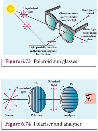
In 1932, an American scientist Edwin Land developed polarisers in the form of sheets. Tourmaline is a natural polarising material. Polaroids are also made artificially. It was discovered that small needle shaped crystals of quinine iodosulphate have the property of polarising light. A number of these crystals with their axes parallel to one another packed in between two transparent plastic sheets serve as a good polaroid. Recently new types of polaroids are prepared in which thin film of polyvinyl alcohol is used. These are colourless crystals which transmit more light, and give better polarisation. Polaroids have many applications as the one shown in Figure 6.73.
Polariser and analyser
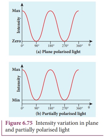
Let us consider an unpolarised beam
of light. The vibrations can be in all possible directions all of them being
perpendicular to the direction of propagation as shown in Figure 6.74. When
this light passes through polaroid P1
the vibrations are restricted to only one plane. The emergent beam can be
further passed through another polaroid P2.
If the polaroid P2 is
rotated about the ray of light as axis, for a particular position of P2 the intensity is maximum.
When the polaroid P2 is
rotated from this position the intensity starts decreasing. There is complete
extinction of the light when P2
is rotated through 90┬║. On further rotation of P2 the light reappears and the intensity increases and
becomes a maximum for a further rotation through 90 ┬║. The light coming out from polaroid P1 is said to be plane polarised. The Polaroid (here P1) which plane polarises the
unpolarised light passing through it is called a polariser. The polaroid (here P2)
which is used to examine whether a beam of light is polarised or not is called
an analyser.
If the intensity of the unpolarised light is I then the intensity of plane polarised light will be (I/2). The other half of intensity is restricted by the polariser.
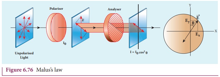
Plane and partially polarised light
In plane polarised light
the intensity varies from maximum to zero for every rotation of 90┬║ of the
analyser as shown in Figure 6.75(a). This is because the
vibrations are allowed in one axis and completely restricted in the
perpendicular axis. On the other hand, if
the intensity of light varies between maximum and minimum for every rotation of 90┬║ of the analyser, the light is said to
be partially polarised light as
shown in Figure 6.75(b). This is because the light is not fully restricted in
that particular axis which shows a minimum intensity.
MalusŌĆÖ law
When a plane polarised light is seen
through an analyser, the intensity of transmitted light varies as the analyser
is rotated through an angle perpendicular to the incident direction. In 1809,
French Physicist E.N Malus discovered that when a beam of plane polarised light
of intensity I0 is
incident on an analyser, the light transmitted of intensity I from the analyser varies directly as
the square of the cosine of the angle ╬Ė between
the transmission axis of polariser and analyser as shown in Figure 6.76. This
is known as MalusŌĆÖ law.
I = I0 cos2 ╬Ė (6.167)

The proof of MalusŌĆÖs law is as
follows. Let us consider the plane of polariser and analyser are inclined to
each other at an angle ╬Ė is as shown
in Figure 6.77. Let I0 be
the intensity and a be the amplitude of
the electric vector transmitted by the polariser. The amplitude a of the incident light has two
rectangular components, acos╬Ė and asin╬Ė which are the
parallel and perpendicular components to the axis of transmission of the
analyser.
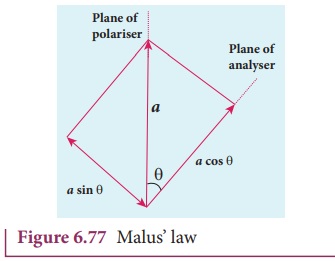
Only the component acos╬Ė
will be transmitted by the analyser. The intensity of light transmitted from
the analyser is proportional to the square of the component of the amplitude transmitted
by the analyser.
I ŌłØ (a cos╬Ė)2
I =k(a cos╬Ė)2
Where k is constant of proportionality.
I =ka2
cos2 ╬Ė
I = I0 cos2 ╬Ė
Where, I0 = ka2 is the maximum intensity of light transmitted from the analyser.
The following are few special cases.
Case (i) When ╬Ė = 0┬║, cos 0 ┬║ = 1, I = I0
When the transmission axis of polarizer
is along that of the analyser, the intensity of light transmitted from the
analyser is equal to the incident light that falls on it from the polariser.
Case (ii) When ╬Ė = 90┬║, cos 90┬║ = 0, I =
0
When the transmission axes of polarizer and analyser are perpendicular to each other, the
intensity of light transmitted from the analyser is zero.
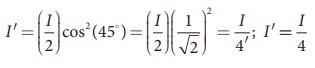
EXAMPLE 6.37
Two polaroids are kept with their
transmission axes inclined at 30┬║. Unpolarised light of intensity I falls on the first polaroid. Find out
the intensity of light emerging from the second polaroid.
Solution
As the intensity of the unpolarised
light falling on the first polaroid is I,
the intensity of polarized light emerging will be, I0 = ( I/2 ).
Let I ŌĆś be the intensity of light emerging from the second polaroid.
MalusŌĆÖ law, I ŌĆ▓ = I0 cos2
╬Ė
Substituting,
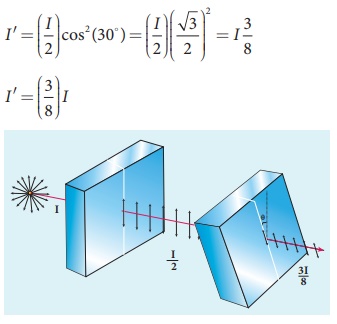
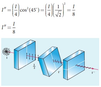
EXAMPLE 6.38
Two polaroids are kept crossed (transmission
axes at 90┬║) to each other.
(i) What will be the intensity of
the light coming out from the second polaroid when an unpolarised light of
intensity I falls on the first
polaroid?
(ii) What will be the intensity of
light coming out from the second polaroid if a third polaroid is kept at 45┬║
inclination to both of them.
Solution
(i) As the intensity of the
unpolarised light falling on the first polaroid is I, the intensity of polarized light emerging from it will be I0
= (I/2).
Let IŌĆś be the intensity of light emerging from the second polaroid.
MalusŌĆÖ law, I ŌĆ▓ = I0 cos2
╬Ė
Here ╬Ė is 90┬║ as the transmission axes are perpendicular to each other.
Substituting,
I0 = ( I/2 ) cos2 (90┬║)= 0
[Ōł┤ cos(90┬║ )= 0]
No light comes out from the second polaroid.
(ii) Let the
first polaroid be P1 and
the second polaroid be P2.
They are oriented at 90┬║. The third polaroid P3 is introduced between them at 45┬║. Let I ŌĆś be the intensity of light emerging
from P3.
Angle between P1 and P3
is 45┬║. The intensity of light coming out from P3 is, I ŌĆ▓ = I0 cos2 ╬Ė
Substituting,
Angle between P3 and P2
is 45┬║. Let IŌĆØ is the intensity of
light coming out from P2 I ŌĆ▓ŌĆ▓ = I ŌĆ▓ cos2 ╬Ė
Here, the intensity of polarized
light existing between P3 and
P2 is 1/4.
Substituting,
Uses of polaroids
ŌĆó Polaroids are used in goggles and cameras to
avoid glare of light.
ŌĆó Polaroids are
useful in three dimensional motion pictures i.e., in holography.
ŌĆó Polaroids are
used to improve contrast in old oil paintings.
ŌĆó Polaroids are
used in optical stress analysis.
ŌĆó Polaroids are
used as window glasses to control the intensity of incoming light.
ŌĆó Polarised laser
beam acts as needle to read/write in compact discs (CDs).
ŌĆó Polaroids produce polarised lights
to be used in liquid crystal display (LCD).
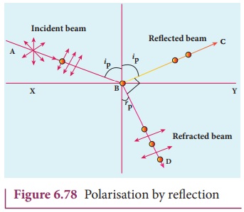
2. Polarisation by reflection
The simplest method of producing
plane polarised light is by reflection. Consider a beam of unpolarised light AB is incident at any angle on the
reflecting glass surface XY.
Vibrations in AB which are parallel to the plane of the diagram are shown by
arrows. The vibrations which are perpendicular to the plane of the diagram and
parallel to the reflecting surface are shown by dots in Figure 6.78. A part of
the light is reflected along BC, and
the rest is refracted along BD. On
examining the reflected beam BC with
an analyser, it is found that the ray is partially plane polarised. When the
light is allowed to be incident at a particular angle the reflected beam is
found to be plane polarised. The angle
of incidence at which the reflected beam is plane polarised is called polarising angle ip.
BrewsterŌĆÖs Law
In 1808, Malus discovered that when
ordinary light is incident on the surface of a transparent medium, the
reflected light is partially plane polarised. The extent of polarisation
depends on the angle of incidence. For a particular angle of incidence, the
reflected light is found to be plane polarised. The angle of incidence at which
a beam of unpolarised light falling on a transparent surface is reflected as a
beam of plane polarised light is called polarising
angle or BrewsterŌĆÖs angle. It is denoted
by ip.
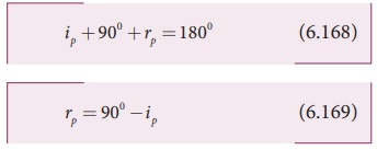
Further, the British Physicist, Sir. David Brewster found that at the incidence of polarising angle, the reflected and transmitted rays are perpendicular to each other. Suppose, ip is the polarising angle and rp is the corresponding angle of refraction. Then from Figure 6.82,
ip + 900 + rp = 1800 (6.168)
rp = 900 ŌłÆip (6.169)
From SnellŌĆÖs law, the refractive
index of the transparent medium is,

where n is the refractive index of
the medium with respect to air.
Substituting the value of rp from Equation 6.163, we
get,
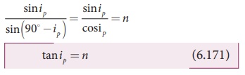
This relation is known as BrewsterŌĆÖs
law. The law states
that the tangent of the polarising angle for a transparent medium is equal to
its refractive index. The value of BrewsterŌĆÖs angle depends on the nature of the
transparent refracting medium and the wavelength of light used.
EXAMPLE 6.39
Find the polarizing angles for (i) glass
of refractive index 1.5 and (ii) water of refractive index 1.33.
Solution
BrewsterŌĆÖs law, tanip = n
For glass, tanip = 1.5; ip
= tanŌłÆ11.5; ip =
56.3┬║
Forwater, tanip = 1.33; ip = tanŌłÆ11.33; ip = 53.1┬║
Pile of plates
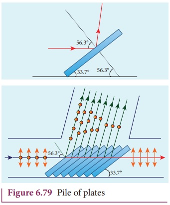
The phenomenon of polarisation by reflection
is used in the construction of pile of plates. It consists of a number of glass
plates placed one over the other in a tube as shown in Figure 6.79. The plates
are inclined at an angle of 33.7┬║(90┬║ -56.3┬║ ) to the axis of the tube. A beam
of unpolarised light is allowed to fall on the pile of plates along the axis of
the tube. So, the angle of incidence of light will be at 56.3┬║ which is the
polarising angle for glass. The vibrations perpendicular to the plane of
incidence are reflected at each surface and those parallel to it are
transmitted. The larger the number of surfaces, the greater is the intensity of
the reflected plane polarised light. The pile of plates is used as a polarizer
and also as an analyser.
EXAMPLE 6.40
What is the angle at which a glass
plate of refractive index 1.65 is to be kept with respect to the horizontal
surface so that an unpolarised light travelling horizontal after reflection
from the glass plate is found to be plane polarised?
Solution
n = 1.65
BrewsterŌĆÖs law, tanip = n
tanip = 1.65; ip
= tanŌłÆ11.65; ip
= 58.80
The inclination with the horizontal
surface is, (900 ŌłÆ58.80 ) = 31.20
3. Polarisation by double refraction
Erasmus Bartholinus, a Danish physicist
discovered that when a ray of
unpolarised light is incident on a calcite crystal, two refracted rays are
produced. Hence, two images of a single object are formed. This phenomenon is
called double refraction as shown
in Figure 6.80. Double refraction is
also called birefringence. This
phenomenon is also exhibited by several
other crystals like quartz, mica etc.
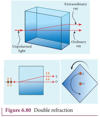
When an ink dot on a sheet of paper is viewed through a calcite crystal, two images will be seen. On rotating the crystal, one image remains stationary, while the other rotates around the first. The stationary image is known as the ordinary image O, produced by the refracted rays which obey the laws of refraction, called as ordinary rays. The other image is extraordinary image E, produced by the refracted rays which do not obey the laws of refraction, called as extraordinary rays. The extraordinary ray is found to be plane polarised. Inside a double refracting crystal the ordinary ray travels with same velocity in all directions and the extra ordinary ray travels with different velocities along different directions. A point source inside a refracting crystal produces spherical wavefront corresponding to ordinary ray and elliptical wavefront corresponding to extraordinary ray. Inside the crystal, there is a particular direction in which both the rays travel with same velocity. This direction is called optic axis. Along the optic axis, the refractive index is same for both the rays and there is no double refraction along this direction.
Types of optically active crystals
Crystals like calcite, quartz,
tourmaline and ice having only one optic axis are called uniaxial crystals.
Crystals like mica, topaz, selenite
and aragonite having two optic axes are called biaxial crystals.
Nicol prism
Nicol prism is an optical device
incorporated in optical instruments both for producing and analysing plane
polarised light. The construction of a Nicol prism is based on the phenomenon
of Double refraction and was designed by William Nicol in 1828.
One of the most common forms of the
Nicol prism is made by taking a calcite crystal which is a double refracting
crystal with its length three times its breadth. As shown in Figure 6.81, ABCD represents the principal section of
a calcite crystal. It is cut into two halves along the diagonal so that their
face angles are 72┬║ and 108┬║. The two halves are joined together by a layer of canada balsam, a transparent cement.
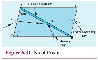
Let us consider a ray of unpolarised
light from monochromatic source such as a sodium vapour lamp is incident on the
face AC of the Nicol prism. Double
refraction takes place and the ray is split into ordinary and extraordinary rays.
They travel with different velocities. The refractive index of the crystal for
the ordinary ray (monochromatic sodium light) is 1.658 and for extraordinary
ray is 1.486. The refractive index of canada balsam is 1.523. Canada balsam
does not polarise light.
The ordinary ray is total internally
reflected at the layer of canada balsam and is prevented from emerging from the
other face. The extraordinary ray alone is transmitted through the crystal
which is plane polarised.
Uses of Nicol prism
ŌĆó It produces plane
polarised light and functions as a polariser
ŌĆó It can also be used to analyse the
plane polarised light i.e used at an analyser.
Drawbacks of Nicol prism
ŌĆó Its cost is very
high due to scarity of large and flawless calcite crystals
ŌĆó Due to
extraordinary ray passing obliquely through it, the emergent ray is always
displaced a little to one side.
ŌĆó The effective
field of view is quite limited
ŌĆó Light emerging out of it is not
uniformly plane polarised.
4. Polarisation by scattering
The light from a clear blue portion
of the sky shows a rise and fall of intensity when viewed through a polaroid
which is rotated. This is because of sunlight, which has changed its direction
(having been scattered) on encountering the molecules of the earthŌĆÖs
atmosphere. As Figure 6.81 shows, the incident sunlight is unpolarised. The
electric field of light interact with the electrons present in the air
molecules.
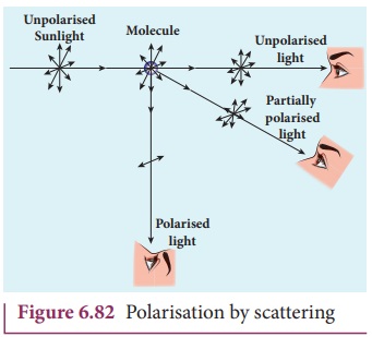
Under the influence of the electric field
of the incident wave the electrons in the molecules acquire components of
motion in both these directions. We have shown an observer looking at 90┬░ to
the direction of the sun. Clearly, charges accelerating parallel do not radiate
energy towards this observer since their acceleration has no transverse
component. The radiation scattered by the molecule is therefore polarized perpendicular to the plane of the
Figure 6.82. This explains the reason for polarisation of sunlight by
scattering.
Related Topics