Chapter: 12th Physics : UNIT 7 : Wave Optics
Wave Nature of Light
WAVE NATURE OF LIGHT
Light is a transverse,
electromagnetic wave. The wave nature of light was first illustrated through
experiments on interference and diffraction. Like all electromagnetic waves,
light can travel through vacuum. The transverse nature of light is demonstrated
in polarization.
1. Wave optics
Wave optics deals with the wave characteristics
of light. With the help of wave optics, we are going to learn in details the
phenomena of interference, diffraction and polarization. Even the law of
reflection and refraction are proved only with the help of wave optics. Though
light propagates as a wave, its direction of propagation is still represented
as a ray.
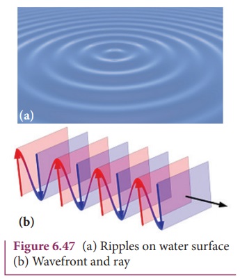
An example for wave propagation is
the spreading of circular ripples on the surface of still water from a point at
which a stone is dropped. The molecules or particles of water are moving only
up and down (oscillate) when a ripple passes out that part. All these particles
on the circular ripple are in the same phase of vibration as they are all at
the same distance from the center. The ripple represents a wavefront as shown
in Figure 6.47(a). A wavefront is the locus of points which
are in the same state or phase of vibration. When a wave propagates it is
treated as the propagation of wavefront. The wavefront is always perpendicular
to the direction of the propagation of the wave. As the direction of ray is in
the direction of propagation of the wave, the wavefront is always perpendicular
to the ray as shown in Figure 6.47(b).
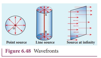
The shape of a wavefront observed at
a point depends on the shape of the source and also the distance at which the
source is located. A point source located at a finite distance gives spherical
wavefronts. An extended (or) line source at finite distance gives cylindrical
wavefronts. The plane wavefronts are received from any source that is located
at infinity as shown in Figure 6.48.
2. Huygens’ Principle
Huygens principle is a geometrical
construction which gives the shape of the wavefront at any time if we know its
shape at t = 0. According to Huygens principle, each point of the wavefront is the
source of secondary wavelets emanating from these points spreading out in all
directions with the speed of the wave. These are called as secondary wavelets.
The common tangent, in other words the envelope to all these wavelets gives the
position and shape of the new wavefront at a later time. Thus, Huygens’
principle explains the propagation of a wavefront.
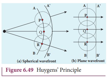
The propagation of a spherical and
plane wavefront is explained in using Huygens’ principle. Let, AB be the wavefront at a time, t = 0. According to Huygens’ principle,
every
point on AB acts
as a source of secondary wavelet which travels with the speed of the wave
(speed of light c). To find the
position of the wavefront after a time t,
circles of radius equal to ct are
drawn with points P, Q, R ... etc., as centers on AB. The tangent or forward envelope A’ B’
of the small circles is the new wavefront at that instant.
The wavefront A’ B’ will be a spherical
wavefront from a point object which is at a finite distance as shown in Figure
49(a) and it is a plane wavefront if the source of light is at a large distance
(infinity) as shown in Figure 6.49(b).
There is one shortcoming in the
above Huygens’ construction for propagation of a wavefront. It could not
explain the absence of backwave which also arises in the above construction.
According to electromagnetic wave theory, the backwave is ruled out inherently.
However, Huygens’ construction diagrammatically explains the propagation of the
wavefront.
3. Proof for laws of reflection using Huygens’ Principle
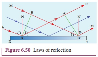
Let us consider a parallel beam of
light, incident on a reflecting plane surface such as a plane mirror XY as shown in Figure 6.50. The incident
wavefront is AB and the reflected wavefront
is A’ B’ in the same medium. These wavefronts are perpendicular to the
incident rays L, M and reflected rays L’ ,
M ‘ respectively. By the time point A of the incident wavefront touches the
reflecting surface, the point B is
yet to travel a distance BB’ to touch
the reflecting surface at B’ . When
the point B falls on the reflecting
surface at B’ , the point A would have reached A’ .
This is applicable to all the points
on the wavefront. Thus, the reflected wavefront A’ B’ emanates as a plane
wavefront. The two normals N and N ‘ are considered at the points where
the rays L and M fall on the reflecting surface. As reflection happens in the same
medium, the speed of light is same before and after the reflection. Hence, the
time taken for the ray to travel from B to
B’ is the same as the time taken for
the ray to travel from A to A’ . Thus, the distance BB’ is equal to the distance AA’ ; (AA’ = BB’) .
(i) The incident rays, the reflected
rays and the normal are in the same plane.
(ii) Angle of incidence,
‚àÝi = ‚àÝNAL = 90¬∫ ‚Äì ‚àÝNAB = ‚àÝ BAB‚Äô
Angle of reflection,
‚àÝr = ‚àÝ N ‚Äò B‚ÄôM ‚Äò = 90¬∫ ‚Äì‚àÝN ‚Äò B‚ÄôA‚Äô = ‚àÝ A‚ÄôB‚ÄôA
For the two right angle triangles, ∆
ABB‚Äô and ‚àÜ B‚ÄôA‚ÄôA , the right angles, ‚àÝB and ‚àÝ A‚Äô are equal, (‚àÝB and ‚àÝ A‚Äô = 90¬∫); the two sides, AA‚Äô
and BB’ are equal, (AA’ =
BB’); the side AB’ is the common.
Thus, the two triangles are congruent. As per the property of congruency, the
two angles, ‚àÝ BAB‚Äô and ‚àÝ A‚Äô B‚ÄôA
must also be equal.

i= r (6.1)
Hence, the laws of reflection are
proved.
4. Proof for laws of refraction using Huygens’ Principle
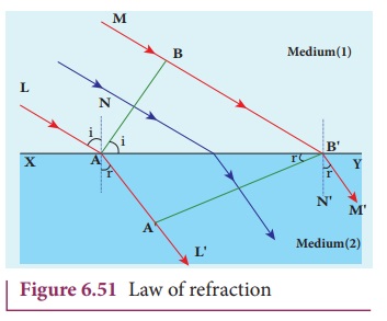
Let us consider a parallel beam of
light is incident on a refracting plane surface XY such as a glass surface as shown in Figure 6.51. The incident wavefront
AB is in rarer medium (1) and the
refracted wavefront A’ B’ is in denser medium (2) These
wavefronts are perpendicular to the incident rays L, M and refracted rays L’,M
‘ respectively. By the time the point A
of the incident wavefront touches the refracting surface, the point B is yet to travel a distance BB’ to touch the refracting surface at B’.
When the point B falls on the refracting surface at B’, the point A would
have reached A’ in the other medium.
This is applicable to all the points on the wavefront. Thus, the refracted
wavefront A’ B’ emanates as a plane wavefront. The two normals N and N ‘ are considered at the points where the rays L and M fall on the refracting surface. As refraction happens from rarer
medium (1) to denser medium (2), the speed of light is v1 and v2
before and after refraction and v1
is greater than v2 (v1>v2). But, the time taken t for the ray to travel from B
to B’ is the same as the time
taken for the ray to travel from A to
A’ .

(i) The incident rays, the refracted
rays and the normal are in the same plane.
(ii) Angle of incidence,
i = ‚àÝNAL = 90¬∫ ‚Äì ‚àÝNAB = ‚àÝ BAB‚Äô
Angle of refraction,
r = ‚àÝ N
‚ÄòB‚ÄôM ‚Äò = 90¬∫ ‚Äì ‚àÝ N
‚ÄòB‚ÄôA‚Äô = ‚àÝA‚ÄôB‚ÄôA
For the two right angle triangles ∆ ABB’ and ∆ B’A’A ,

Here, c is speed of light in vacuum. The ratio c/v is the constant,
called refractive index of the medium. The refractive index of medium (1) is, c/v1
= n1 and that of medium
(2) is, c/v2 = n2.
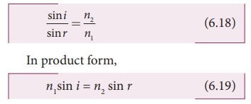
Hence, the laws of refraction are
proved.
In the same way the laws of
refraction can also be proved for wavefront travelling from denser to rarer
medium.
Light travels with greater speed in
rarer medium and lesser speed in denser medium Hence, the wavelength of the
light is longer in rarer medium and shorter in denser medium.

If light of a particular frequency
travels through different media, then, its frequency remains unchanged in all
the media. Only the wavelength changes according to speed of light in that
medium.
EXAMPLE 6.23
The wavelength of light from sodium
source in vacuum is 5893√Ö.What are its (a) wavelength, (b) speed and (c)
frequency when this light travels in water which has a refractive index of
1.33.
Solution
The refractive index of vacuum, n1 = 1
The wavelength in vacuum, λ1 = 5893 Å.
The speed in vacuum, c = 3 × 10⁸ m s–1
The refractive index of water, n2 = 1.33
The wavelength of light in water, λ2
The speed of light in water, v2
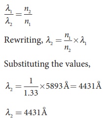
(a) The equation relating the
wavelength and refractive index is,
(b) The equation relating the speed
and refractive index is,
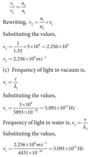
The results show that the frequency
remains same in all media.
Related Topics