Chapter: Television and Video Engineering : Fundamentals of Television
Video Signal Dimensions
VIDEO SIGNAL DIMENSIONS
Figure
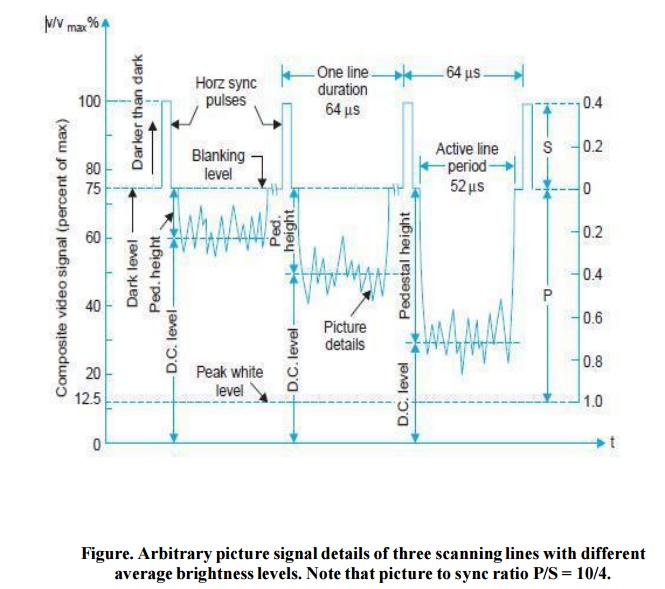
shows the composite video signal details of three different lines each
corresponding to a different brightness level of the scene. As illustrated
there, the video signal is constrained to vary between certain amplitude
limits.
The level
of the video signal when the picture detail being transmitted corresponds to
the maximum whiteness to be handled, is referred to as peak-white level. This
is fixed at 10 to 12.5 percent of the maximum value of the signal while the
black level corresponds to approximately 72 percent.
The sync
pulses are added at 75 percent level called the blanking level. The difference
between the black level and blanking level is known as the ‘Pedestal’. However,
in actual practice, these two levels, being very close, tend to merge with each
other as shown in the figure.
Thus the
picture information may vary between 10 percent to about 75 percent of the
composite video signal depending on the relative brightness of the picture at
any instant. The darker the picture the higher will be the voltage within those
limits.
Note that
the lowest 10 percent of the voltage range (whiter than white range) is not
used to minimize noise effects. This also ensures enough margin for excessive
bright spots to be accommodated without causing amplitude distortion at the
modulator.
At the
receiver the picture tube is biased to ensure that a received video voltage
corresponding to about 10 percent modulation yields complete whiteness at that
particular point on the screen, and an analogous arrangement is made for the
black level.
Besides
this, the television receivers are provided with ‘brightness’ and ‘contrast’
controls to enable the viewer to make final adjustments as he thinks fit.
D.C. component of the video signal.
In
addition to continuous amplitude variations for individual picture elements,
the video signal has an average value or dc component corresponding to the
average brightness of the scene.
In the
absence of dc component the receiver cannot follow changes in brightness, as
the ac camera signal, say for grey picture elements on a black background will
then be the same as a signal for white area on a grey back-ground.
In Fig,
dc components of the signal for three lines have been identified, each
representing a different level of average brightness in the scene. It may be
noted that the break shown in the illustration after each line signal is to
emphasize that dc component of the video signal is the average value for
complete frames rather than lines since the background information of the
picture indicates the brightness of the scene.
Thus Fig.
illustrates the concept of change in the average brightness of the scene with
the help of three lines in separate frames because the average brightness can
change only from frame to frame and not from line to line.
Pedestal height.
As noted
in Fig the pedestal height is the distance between the pedestal level and the
average value (dc level) axis of the video signal. This indicates average brightness
since it measures how much the average value differs from the black level.
Even when
the signal loses its dc value when passed through a capacitor-coupled circuit
the distance between the pedestal and the dc level stays the same and thus it
is convenient to use the pedestal level as the reference level to indicate
average brightness of the scene.
Setting the pedestal level.
The
output signal from the TV camera is of very small amplitude and is passed
through several stages of ac coupled high gain amplifiers before being coupled
to a control amplifier.
Here sync
pulses and blanking pulses are added and then clipped at the correct level to
form the pedestals. Since the pedestal height determines the average brightness
of the scene, any smaller value than the correct one will make the scene darker
while a larger Pedestal height will result in higher average brightness.
The video
control operator who observes the scene at the studio sets the level for the
desired brightness in the reproduced picture which he is viewing on a monitor
receiver. This is known as dc insertion because this amounts to adding a dc
component to the ac signal.
Once the
dc insertion has been accomplished the pedestal Level becomes the black
reference and the pedestal height indicates correct relative brightness for the
reproduced picture. However, the dc level inserted in the control amplifier is
usually Lost in succeeding stages because of capacitive coupling, but still the
correct dc component can
be
reinserted when necessary because the pedestal height remains the same.
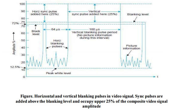
The blanking pulses.
The
composite video signal contains blanking pulses to make the retrace lines
invisible by raising the signal amplitude slightly above the black level (75
percent) during the time the scanning circuits produce retraces.
As
illustrated in Fig. the composite video signal contains horizontal and vertical
blanking pulses to blank the corresponding retrace intervals. The repetition
rate of horizontal blanking pulses is therefore equal to the line scanning
frequency of 15625 Hz.
Similarly
the frequency of the vertical blanking pulses is equal to the field-scanning
frequency of 50 Hz. It may be noted that though the level of the blanking
pulses is distinctly above the picture signal information, these are not used
as sync pulses.
The
reason is that any occasional signal corresponding to any extreme black portion
in the picture may rise above the blanking level and might conceivably
interfere with the synchronization of the scanning generators.
Therefore,
the sync pulses, specially designed for triggering the sweep oscillators are
placed in the upper 25 per cent (75 per cent to 100 per cent of the carrier
amplitude) of the video signal, and are transmitted along with the picture
signal.
Sync pulse and video signal amplitude ratio.
The
overall arrangement of combining the picture signal and sync pulses may be
thought of as a kind of voltage division multiplexing where about 65 per cent
of the carrier amplitude is occupied by the video signal and the upper 25 per
cent by the sync pulses.
Thus, as
shown in Fig. 3.1, the final radiated signal has a picture to sync signal ratio
(P/S) equal to 10/4.
This
ratio has been found most satisfactory because if the picture signal amplitude
is increased at the expense of sync pulses, then when the signal to noise ratio
of the received signal falls, a point is reached when the sync pulse amplitude
becomes insufficient to keep the picture locked even though the picture voltage
is still of adequate amplitude to yield an acceptable picture.
On the
other hand if sync pulse height is increased at the expense of the picture
detail, then under similar conditions the raster remains locked but the picture
content is of too low an amplitude to set up a worthwhile picture.
A ratio
of P/S = 10/4, or thereabout, results in a situation such that when the signal
to noise ratio reaches a certain low level, the sync amplitude becomes
insufficient, i.e., the sync fails at
the same time as the picture ceases to be of entertainment value. This
represents the most efficient use of the television system
Related Topics