Chapter: Television and Video Engineering : Fundamentals of Television
Monochrome Picture Tube
MONOCHROME PICTURE TUBE
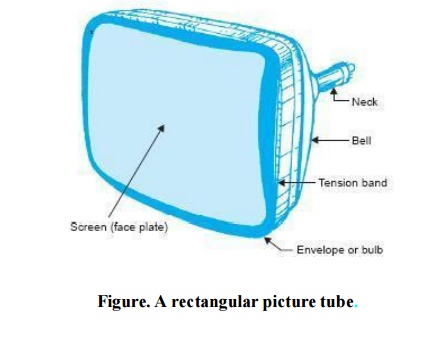
Modern monochrome picture tubes employ electrostatic focusing and electromagnetic deflection. A typical black and white picture tube is shown in Fig. The deflection coils are mounted externally in a specially designed yoke that is fixed close to the neck of the tube.
The coils when fed simultaneously with vertical and horizontal scanning currents deflect the beam at a fast rate to produce the raster. The composite video signal that is injected either at the grid or cathode of the tube, modulates the electron beam to produce brightness variations of the tube, modulates the electron beam to produce brightness variations on the screen.
This results in reconstruction of the picture on the raster, bit by bit, as a function of time. However, the information thus obtained on the screen is perceived by the eye as a complete and continuous scene because of the rapid rate of scanning.
Electron Gun
The various electrodes that constitute the electron gun are shown in Fig. The cathode is indirectly heated and consists of a cylinder of nickel that is coated at its end with thoriated tungsten or barium and strontium oxides.
These emitting materials have low work-function Base within the tube. The control grid (Grid No. 1) is maintained at a negative potential with respect to cathode and controls the flow of electrons from the cathode.
However, instead of a wire mesh structure, as in a conventional amplifier tube, it is a cylinder with a small circular opening to confine the electron stream to a small area. The grids that follow the control grid are the accelerating or screen grid (Grid No. 2) and the focusing grid (Grid No. 3).
These are maintained at different positive potentials with respect to the cathode that vary between + 200 V to + 600 V.All the elements of the electron gun are connected to the base pins and receive their rated voltages from the tube socket that is wired to the various sections of the receiver.

Electrostatic Focussing
The electric field due to the positive potential at the accelerating grid (also known as 1st anode) extends through the opening of the control grid right to the cathode surface. The orientation of this field is such that besides accelerating the electrons down the tube, it also brings all the electrons in the stream into a tiny spot called the crossover.
This is known as the first electrostatic lens action. The resultant convergence of the beam is shown in Fig. The second lens system that consists of the screen grid and focus electrode draws electrons from the crossover point and brings them to a focus at the viewing screen.
The focus anode is larger in diameter and is operated at a higher potential than the first anode. The resulting field configuration between the two anodes is such that the electrons leaving the crossover point at various angles are subjected to both convergent and divergent forces as they more along the axis of the tube.
This in turn alters the path of the electrons in such a way that they meet at another point on the axis. The electrode voltages are so chosen or the electric field is so varied that the second point where all the electrons get focused is the screen of the picture tube. Electrostatic focusing is preferred over magnetic focusing because it is not affected very much by changes in the line voltage and needs no ion-spot correction.
Beam Velocity
In order to give the electron stream sufficient velocity to reach the screen material with proper energy to cause it to fluoresce, a second anode is included within the tube.
This is a conductive coating with colloidal graphite on the inside of the wide bell of the tube. This coating, called aquadag, usually extends from almost half-way into the narrow neck to within 3 cm of the fluorescent screen as shown in Fig.
It is connected through a specially provided pin at the top or side of the glass bell to a very high potential of over 15 kV. The exact voltage depends on the tube size and is about 18 kV for a 48 cm monochrome tube.
The electrons that get accelerated under the influence of the high voltage anode area, attain very high velocities before they hit the screen.
Most of these electrons go straight and are not collected by the positive coating because its circular structure provides a symmetrical accelerating field around all sides of the beam.
The kinetic energy gained by the electrons while in motion is delivered to the atoms of the phosphor coating when the beam hits the screen. This energy is actually gained by the outer valence electrons of the atoms and they move to higher energy levels.
While returning to their original levels they give out energy in the form of electromagnetic radiation, the frequency of which lies in the spectral region and is thus perceived by the eye as spots of light of varying intensity depending on the strength of the electron beam bombarding the screen.
Because of very high velocities of the electrons which hit the screen, secondary emission takes place. If these secondary emitted electrons are not collected, a negative space charge gets formed near the screen which prevents the primary beam from arriving at the screen.
The conductive coating being at a very high positive potential collects the secondary emitted electrons and thus serves the dual purpose of increasing the beam velocity and removing unwanted secondary electrons.
The path of the electron current flow is thus from cathode to screen, to the conductive coating through the secondary emitted electrons and back to the cathode through the high voltage supply.
A typical value of beam current is about 0.6 mA with 20 kV applied at the aquadag coating.
Related Topics