Chapter: Television and Video Engineering : Fundamentals of Television
Image Orthicon
IMAGE ORTHICON
This tube makes use of the high photo emissive sensitivity obtainable from photocathodes, image multiplication at the target caused by secondary emission and an electron multiplier.
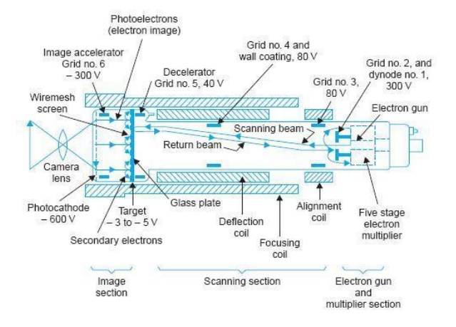
A sectional view of an image orthicon is shown in Fig. It has three main sections: image section, scanning section and electron gun-cum-multiplier section. (i) Image Section The inside of the glass face plate at the front is coated with a silver, antimony coating sensitized with cesium, to serve as photocathode.
Light from the scene to be televised is focused on the photocathode surface by a lens system and the optical image thus formed results in the release of electrons from each point on the photocathode in proportion to the incident light intensity. Photocathode surface is semitransparent and the light rays penetrate it to reach its inner surface from where electron emission takes place.
Since the number of electrons emitted at any point in the photocathode has a distribution corresponding to the brightness of the optical image, an electron image of the scene or picture gets formed on the target side of the photo coating and extends towards it. Through the conversion efficiency of the photocathode is quite high, it cannot store charge being a conductor.
For this reason, the electron image produced at the photocathode is made to move towards the target plate located at a short distance from it. The target plate is made of a very thin sheet of glass and can store the charge received by it.
This is maintained at about 400 volts more positive with respect to the photocathode, and the resultant electric field gives the desired acceleration and motion to the emitted electrons towards it. The electrons, while in motion, have a tendency to repel each other and thin can result in distortion of the information now available as charge image. To prevent this divergence effect an axial magnetic field, generated in this region by the ‘long focus coil’ is employed.
This magnetic field imparts helical motion of increasing pitch and focuses the emitted electrons on the target into a well-defined electron image of the original optical image. The image side of the target has a very small deposit of cesium and thus has a high secondary emission ratio.
Because of the high velocity attained by the electrons while in motion from photocathode to the target plate, secondary emission results, as the electrons bombard the target surface.
These secondary electrons are collected by a wire-mesh screen, which is located in front of the target on the image side and is maintained at a slightl y higher potential with respect to the target.
The wire-mesh screen has about 300 meshes per cm 2 with an open area of 50 to 75 per cent, so that the screen wires do not interfere with the electron image.
The secondary electrons leave behind on the target plate surface, a positive charge distribution, corresponding to the light intensity distribution on the original photocathode. For storage action this charge on the target plate should not spread laterally over its surface, during the storage time, since this would destroy the resolution of the device.
To achieve this the target is made out of extremely thin sheet of glass. The positive charge distribution builds up during the frame storage time (40 ms) and thus enhances the sensitivity of the tube. It should be clearly understood, that the light from the scene being televised continuously falls on the photocathode, and the resultant emitted electrons on reaching the target plate cause continuous secondary emission. This continuous release of electrons results in the building up of positive charge on the target plate.
Because of the high secondary emission ratio, the intensity of the positive charge distribution is four to five times more as compared to the charge liberated by the photo cathode.
This increase in charge density relative to the charge liberated at the photocathode is known as ‘image multiplication’ and contributes to the increased sensitivity of image orthicon. As shown in Fig., the two-sided target has the charge image on one side while an electron beam scans the opposite side.
Thus, while the target plate must have high resistivity laterally for storage action, it must have low resistivity along its thickness, to enable the positive charge to conduct to the other side which is scanned.
It is for this reason that the target plate is very thin, with thickness close to 0.004 mm. Thus, whatever charge distribution builds up on one side of the target plate due to the focused image, appears on the other side, which is scanned, and it is from here that the video signal is obtained.
(ii) Scanning Section
The electron gun structure produces a beam of electrons that is accelerated towards the target. As indicated in the figure, positive accelerating potentials of 80 to 330 volts are applied to grid 2, grid 3, and grid 4 which is connected internally to the metalized conductive coating on the inside wall of the tube. The electron beam is focused at the target by magnetic field of the external focus coil and by voltage supplied to grid 4. The alignment coil provides magnetic field that can be varied to adjust the scanning beam’s position, if necessary, for correct location.
Deflection of electron beams to scan the entire target plate is accomplished by magnetic fields of vertical and horizontal deflecting coils mounted on yoke external to the tube. These coils are fed from two oscillators, one working at 15625 Hz, for horizontal deflection, and the other operating at 50 Hz, for vertical deflection. The target plate is close to zero potential and therefore electrons in the scanning beam can be made to stop their forward motion at its surface and then return towards the gun structure.
The grid 4 voltage is adjusted to produce uniform deceleration of electrons for the entire target area. As a result, electrons in the scanning beam are slowed down near the target. This eliminates any possibility of secondary emission from this side of the target plate.
If a certain element area on the target plate reaches a potential of, say, 2 volts during the storage time, then as a result of its thinness the scanning beam ‘sees’ the charge deposited on it, part of which gets diffused to the scanned side and deposits an equal number of negative charges on the opposite side.
Thus out of the total electrons in the beam, some get deposited on the target plate, while the remaining stop at its surface and turn back to go towards the first electrode of the electron multiplier. Because of low resistivity across the two sides of the target, the deposited negative charge neutralizes the existing positive charge in less than a frame time.
The target can again become charged as a result of the incident picture information, to be scanned during the successive frames. As the target is scanned element by element, if there are no positive charges at certain points, all the electrons in the beam return towards the electron gun and none gets deposited on the target plate.
The number of electrons, leaving cathode of the gun, is practically constant, and out of this, some get deposited and remaining electrons, which travel backwards provide signal current that varies in amplitude in accordance with the picture information.
Obviously then, the signal current is maximum for black areas on the picture, because absence of light from black areas on the picture does not result in any emission on the photocathode, and there is no secondary emission at the corresponding points on the target, and no electrons are needed from the beam to neutralize them.
On the contrary for high light areas, on the picture, there is maximum loss of electrons from the target plate, due to secondary emission, and this results in large deposits of electrons from the beam and this reduces the amplitude of the returning beam current. The resultant beam current that turns away from the target, is thus, maximum for black areas and minimum for bright areas on the picture. High intensity light causes large charge imbalance on the glass target plate.
The scanning beam is not able to completely neutralize it in one scan. Therefore the earlier impression persists for several scans. Image Resolution. It may be mentioned at this stage that since the beam is of low velocity type, being reduced to near zero velocity in the region of the target it is subjected to stray electric fields in its vicinity, which can cause defocusing and thus loss of resolution.
Also on contact with the target, the electrons would normally glide along its surface tangentially for a short distance and the point of contact becomes ill defined. The beam must strike the target at right angle at all points of the target, for better resolution. These difficulties are overcome in the image-orthicon by the combined action of electrostatic field because of potential on grid 4, and magnetic field of the long focusing coil.
The interaction of two fields gives rise to cyclical motion to the beam in the vicinity of target, which then hits it at right angle no matter which point is being scanned. This very much improves the resolving capability of the picture tube.
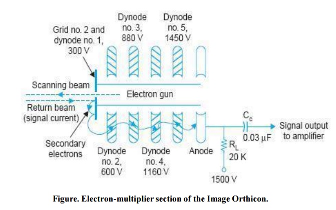
(iii) Electron Multiplier
The returning stream of electrons arrive at the gun close to the aperture from which electron beam emerged. The aperture is a part of a metal disc covering the gun electrode. When the returning electrons strike the disc which is at a positive potential of about 300 volts, with respect to the target, they produce secondary emission.
The disc serves as first stage of the electron multiplier. Successive stages of the electron multiplier are arranged symmetrically around and back of the first stage. Therefore secondary electrons are attracted to the dynodes at progressively higher positive potentials. Five stages of multiplication are used, details of which are shown in Fig. Each multiplier stage provides a gain of approximately 4 and thus a total gain of (4) 5 ≈ 1000 is obtained at the electron multiplier. This is known as signal multiplication.
The multiplication so obtained maintains a high signal to noise ratio. The secondary electrons are finally collected by the anode, which is connected to the highest supply voltage of + 1500 volts in series with a load resistance R L . The anode current through R L has the same variations that are present in the return beam from the target and amplified by the electron multiplier.
Therefore voltage across R L is the desired video signal; the amplitude of which varies in accordance with light intensity variations of scene being televised. The output across R L is capacitive coupled to the camera signal amplifier. With R L = 20 K-ohms and typical dark and high light currents of magnitudes 30 μA and 5 μA respectively, the camera output signal will have an amplitude of 500 mV peak-to-peak.
Field Mesh Image Orthicon. The tube described above is a non-field mesh image orthicon. In some designs an additional pancake-shaped magnetic coil is provided in front of the face plate. This is connected in series with the main focusing coil.
The location of the coil results in a graded magnetic field such that the optically focused photocathode image is magnified by about 1.5 times. Thus the charge image produced on the target plate is bigger in size and this results in improved resolution and better overall performance. Such a camera tube is known as a field mesh Image Orthicon.
Light Transfer Characteristics and Applications
During the evolution of image orthicon tubes, two separate types were developed, one with a very close target-mesh spacing (less than 0.001 cm) and the other with somewhat wider spacing.
The tube, with very close target mesh spacing, has very high signal to noise ratio but this is obtained at the expense of sensitivity and contrast ratio.
This is a worthwhile exchange where lighting conditions can be controlled and picture quality is of primary importance. This is generally used for live shows in the studios.
The other type with wider target-mesh spacing has high sensitivity and contrast ratio with more desirable spectral response.
This tube has wider application for outdoor or other remote pickups where a wide range of lighting conditions have to be accommodated. More recent tubes with improved photocathodes have sensitivities several times those of previous tubes and much improved spectral response.
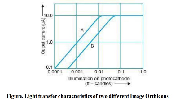
Overall transfer characteristics of such tubes are drawn in Fig. Tube ‘A’ is intended primarily for outdoor pick-ups where as tube ‘B’ is much suited for studio use and requires strong illumination.
The knee of the transfer characteristics is reached when the illumination causes the target to be fully charged with respect to the mesh between successive scans by the electron beam.
The tube is sometimes operated slightly above the knee, to obtain the black border effect (also known as Halo effect) around the high light areas of the target.
Related Topics