Chapter: Television and Video Engineering : Fundamentals of Television
Vertical Sync Details
VERTICAL SYNC DETAILS
The
vertical sync pulse train added after each field is somewhat complex in nature.
The reason for this stems from the fact that it has to meet several exacting
requirements.
Therefore,
in order to fully appreciate the various constituents of the pulse train, the
vertical sync details are explored step by step while explaining the need for
its various components.
The basic
vertical sync added at the end of both even add odd fields is shown in Fig. Its
width has to be kept much larger than the horizontal sync pulse, in order to
derive a suitable field sync pulse at the receiver to trigger the field sweep
oscillator. The standards specify that the vertical sync period should be 2.5
to 3 times the horizontal line period. If the width is less than this, it
becomes difficult to distinguish between horizontal and vertical pulses at the
receiver.
In color
TV transmission a short sample (8 to 10 cycles) of the color subcarrier
oscillator output is sent to the receiver for proper detection of color signal
sidebands.
This is
known as color burst and is located at the back porch of the horizontal
blanking pedestal. If the width is greater than this, the transmitter must
operate at peak power for an unnecessarily long interval of time. In the 625
line system 2.5 line period (2.5 × 64 = 160 µ s) has been allotted for the
vertical sync pulses.
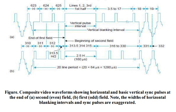
Thus a
vertical sync pulse commences at the end of 1st half of 313th line (end of
first field) and terminates at the end fo 315th line. Similarly after an exact
interval of 20 ms (one field period) the next sync pulse occupies line numbers
1st, 2nd and 1st half of third, just after the second field is over.
Note that
the beginning of these pulses has been aligned in the figure to signify that
these must occur after the end of vertical stroke of the beam in each field, i.e., after each 1/50th of a second.
This
alignment of vertical sync pulses, one at the end of a half-line period and the
other after a full line period (see Fig.)results in a relative misalignment of
the horizontal sync pulses and they do not appear one above the other but occur
at half-line intervals with respect to each other.
However,
a detailed examination of the pulse trains in the two fields would show that
horizontal sync pulses continue to occur exactly at 64 µ s intervals (except
during the vertical sync pulse periods) throughout the scanning period from
frame to frame and the apparent shift of 32 µ s is only due to the alignment of
vertical sync instances in the figure.
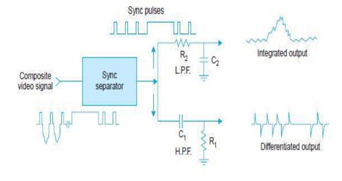
As
already mentioned the horizontal sync information is extracted from the sync
pulse train by differentiation, i.e.,
by passing the pulse train through a high-pass filter. Indeed pulses
corresponding to the differentiated leading edges of sync pulses are used to
synchronize the horizontal scanning oscillator.
The
process of deriving these pulses is illustrated in Fig. Furthermore, receivers
often use mono stable multi-vibrators to generate horizontal scan, andso a
pulse is required to initiate each and every cycle of the horizontal oscillator
in the receiver. This brings out the first and most obvious shortcoming of the
waveforms shown in Fig.
The
horizontal sync pulses are available both during the active and blanked line
periods but there are no sync pulses (leading edges) available during the 2.5
line vertical sync period.
Thus the
horizontal sweep oscillator that operates at 15625 Hz, would tend to step out
of synchronism during each vertical sync period. The situation after an odd
field is even worse.
As shown
in Fig. the vertical blanking period at the end of an odd field begins midway
through a horizontal line. Consequently, looking further along this waveform,
we see that the leading edge of the vertical sync pulse comes at the wrong time
to provide synchronization for the horizontal oscillator.
Therefore,
it becomes necessary to cut slots in the vertical sync pulse at
half-line-intervals to provide horizontal sync pulses at the correct instances
both after even and odd fields.
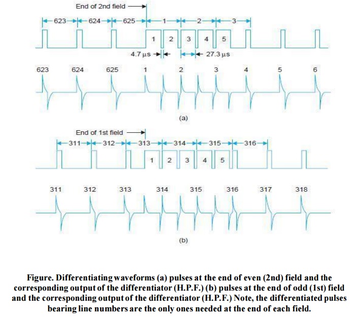
The
technique is to take the video signal amplitude back to the blanking level 4.7
µ s before the line pulses are needed. The waveform is then returned back to
the maximum level at the moment the line sweep circuit needs synchronization.
Thus five
narrow slots of 4.7 µ s width get formed in each vertical sync pulse at
intervals of 32 µ s. The trailing but rising edges of these pulses are actually
used to trigger the horizontal oscillator.
The
resulting waveforms together with line numbers and the differentiated output of
both the field trains is illustrated in Fig.
This
insertion of short pulses is known as notching or serration of the broad field
pulses. Note that though the vertical pulse has been broken to yield horizontal
sync pulses, the effect on the vertical pulse is substantially unchanged.
It still
remains above the blanking voltage level all of the time it is acting. The
pulse width is still much wider than the horizontal pulse width and thus can be
easily separated at the receiver.
Returning
to Fig. it is seen that each horizontal sync pulse yields a positive spiked
output from its leading edge and a negative spiked pulse from its trailing
edge. Time-constant of the differentiating circuit is so chosen, that by the
time a trailing edge arrives, the pulse due to the leading edge has just about
decayed.
The
negative-going triggering pulses may be removed with a diode since only the
positive going pulses are effective in locking the horizontal oscillator.
However, the pulses actually utilized are the ones that occur sequentially at
64 µ s intervals. Such pulses are marked with line numbers for both the fields.
Note that during the intervals of serrated vertical pulse trains, alternate
vertical spikes are utilized.
The
pulses not used in one field are the ones utilized during the second field.
This happens because of the half-line difference at the commencement of each
field and the fact that notched vertical sync pulses occur at intervals of 32 µ
s and not 64 µ s as required by the horizontal sweep oscillator.
The
pulses that come at a time when they cannot trigger the oscillator are ignored.
Thus the requirement of keeping the horizontal sweep circuit locked despite
insertion of vertical sync pulses is realized.
Now we
turn to the second shortcoming of the waveform of Fig. First it must be
mentioned that synchronization of the vertical sweep oscillator in the receiver
is obtained from vertical sync pulses by integration.
This is
illustrated in Fig. where the time-constant R2C2 is chosen to be large compared
to the duration of horizontal pulses but not with respect to width of the
vertical sync pulses.
The
integrating circuit may equall y be looked upon as a low pass filter, with a
cut-off
frequency
such that the horizontal sync pulses produce very little output, while the
vertical pulses have a frequency that falls in the pass-band of the filter.
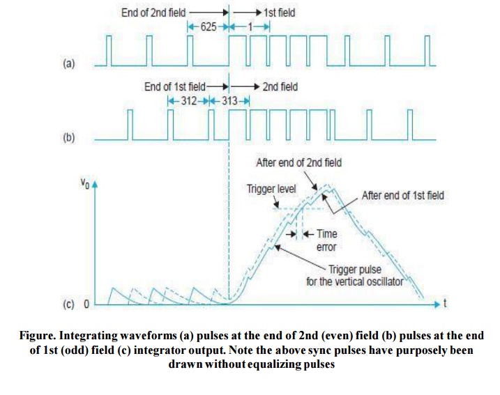
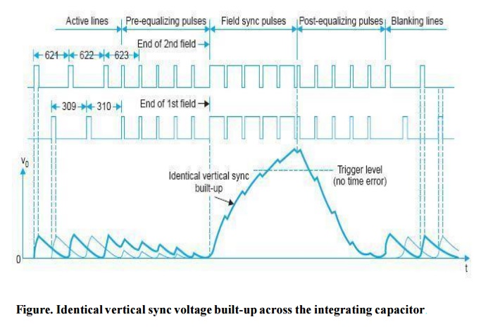
The voltage
built across the capacitor of the low-pass filter (integrating circuit)
corresponding to the sync pulse trains of both the fields is shown in Fig. Note
that each horizontal pulse causes a slight rise in voltage across the capacitor
but this is reduced to zero by the time the next pulse arrives.
This is
so, because the charging period for the capacitor is only 4.7 µ s and the
voltage at the input to the integrator remains at zero for the rest of the
period of 59.3 µ s.
Hence
there is no residual voltage across the vertical filter (L.P. filter) due to
horizontal sync pulses. Once the broad serrated vertical pulse arrives the
voltage across the output of the filter starts increasing. However, the built
up voltage differs for each field.
The
reason is not difficult to find. At the beginning of the first field (odd
field) the last horz sync pulse corresponding to the beginning of 625th line is
separated from the 1st vertical pulse by full one line and any voltage
developed across the filter will have enough time to return to zero before the
arrival of the first vertical pulse, and thus the filter output voltage builds
up from zero in response to the five successive broad vertical sync pulses.
The
voltage builds up because the capacitor has more time to charge and only 4.7 µ
s to discharge. The situation, however, is not the same for the beginning of
the 2nd (even) field. Here the last horizontal pulse corresponding to the
beginning of 313th line is separated from the first vertical pulse by only
half-a-line.
The
voltage developed across the vertical filter will thus not have enough time to
reach zero before the arrival of the first vertical pulse, which means that the
voltage build-up does not start from zero, as in the case of the 1st field. The
residual voltage on account of the half line discrepancy gets added to the
voltage developed on account of the broad vertical pulses and thus the voltage
developed across the output filter is some what higher at each instant as
compared to the voltage developed at the beginning of the first-field.
This is
shown in dotted chain line in Fig. The vertical oscillator trigger potential
level marked as trigger level in the diagram (Fig. )intersects the two filter
output profiles at different points which indicates that in the case of second
field the oscillator will get triggered a fraction of a second too soon as
compared to the first field. Note that this inequality in potential levels for
the two fields continues during the period of discharge of the capacitor once the
vertical sync pulses are over and the horizontal sync pulses take-over.
Though
the actual time difference is quite short it does prove sufficient to upset the
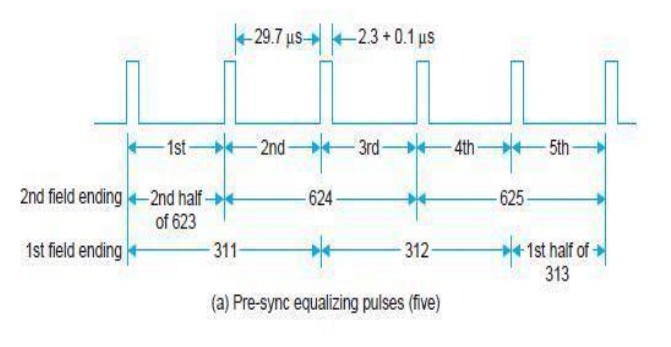
desired interlacing sequence. End of 2nd field 1st field Equalizing pulses. To take care of this drawback which occurs on
account of the half-a-line discrepancy five narrow pulses are added on either
side of the vertical sync pulses.
These are
known as pre-equalizing and post-equalizing pulses. Each set consists of five
narrow pulses occupying 2.5 lines period on either side of the vertical sync
pulses. Pre-equalizing and post equalizing pulse details with line numbers
occupied by them in each field are given in Fig.
The
effect of these pulses is to shift the half-line discrepancy away both from the
beginning and end of vertical sync pulses. Pre-equalizing pulses being of 2.3 µ
s duration result in the discharge of the capacitor to essentially zero voltage
in both the fields, despite the half-line discrepancy before the voltage
build-up starts with the arrival of vertical sync pulses.
This is
illustrated in Fig. Post-equalizing pulses are necessary for a fast discharge
of the capacitor to ensure triggering of the vertical oscillator at proper
time. If the decay of voltage across the capacitor is slow as would happen in
the absence of post-equalizing pulses, the oscillator may trigger at the
trailing edge which may be far-away from the leading edge and this could lead
to an error in triggering.
Thus with
the insertion of narrow pre and post equalizing pulses, the voltage rise and
fall profile is essentially the same for both the field sequences (see Fig.)
and the vertical oscillator is triggered at the proper instants, i.e., exactly at an interval of 1/50th
of a second.
This
problem could possibly also be solved by using an integrating circuit with a
much larger time constant, to ensure that the capacitor remains virtually
uncharged by the horizontal pulses. However, this would have the effect of
significantly reducing the integrator output for vertical pulses so that a
vertical sync amplifier would have to be used.
In a
broadcasting situation, there are thousands of receivers for every transmitter.
Consequently it is much more efficient and economical to cure this problem in
one transmitter than in thousands of receivers. This, as explained above, is
achieved by the use of pre and post equalizing pulses.
The
complete pulse trains for both the fields incorporating equalizing pulses are
shown in
.From the comparison of the horizontal and vertical output
pulse forms shown in Fig and it appears that the
vertical trigger pulse (output of the low-pass filter) is not very sharp but
actually it is not so. The scale hosen exaggerates the extent of the vertical
pulses. The voltage build-up period is only 160 µ s and so far as the vertical
synchronizing oscillator is concerned this pulse occurs rapidly and
represents a sudden change in voltage which decays very fast.
The
polarity of the pulses as obtained at the outputs of their respective fields
may not be suitable for direct application in the controlled synchronizing
oscillator and might need inversion

Related Topics