Chapter: Television and Video Engineering : Fundamentals of Television
Interlaced Scanning
INTERLACED SCANNING
Interlaced
scanning. In television pictures an effective rate of 50 vertical scans per
second is utilized to reduce flicker. This is accomplished by increasing the
downward rate of travel of the scanning electron beam, so that every alternate
line gets scanned instead of every successive line.
Then,
when the beam reaches the bottom of the picture frame, it quickly returns to
the top to scan those lines that were missed in the previous scanning. Thus the
total number of lines are divided into two groups called ‘fields’. Each field
is scanned alternately. This method of scanning is known as interlaced scanning
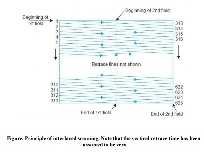
and is illustrated in Fig. It reduces flicker to an acceptable level since the
area of the screen is covered at twice the rate.
This is
like reading alternate lines of a page from top to bottom once and then going
back to read the remaining lines down to the bottom.In the 625 lime monochrome
system, for successful interlaced scanning, the 625 lines of each frame or
picture are divided into sets of 312.5 lines and each set is scanned alternately
to cover the entire picture area.
To
achieve this the horizontal sweep oscillator is made to work at a frequency of
15625 Hz (312.5 × 50 = 15625) to scan the same number of lines per frame
(15625/25 = 625 lines), but the vertical sweep circuit is run at a frequency of
50 instead of 25 Hz.
Note that
since the beam is now deflected from top to bottom in half the time and the
horizontal oscillator is still operating at 15625 Hz, only half the total
lines, i.e., 312.5 (625/2 = 312.5) get scanned during each vertical sweep.
Since the
first field ends in a half line and the second field commences at middle of the
line on the top of the target plate or screen (see Fig), the beam is able to
scan the remaining 312.5 alternate lines during its downward journey. In all
then, the beam scans 625 lines (312.5 × 2 = 625) per frame at the same rate of
15625 lines (312.5 × 50 = 15625) per second. Therefore, with interlaced
scanning the flicker effect is eliminated without increasing the speed of
scanning, which in turn does not need any increase in the channel bandwidth. It
may be noted that the frame repetition rate of 25 (rather than 24 as used in
motion pictures) was chosen to make the field frequency equal to the power line
frequency of 50 Hz.
This
helps in reducing the undesired effects of hum due to pick up from the mains,
because then such effects in the picture stay still, instead of drifting up or
down on the screen.
In the
American TV system, a field frequency of 60 was adopted because the suppl y
frequency is 60 Hz in USA. This brings the total number of lines scanned per
second ((525/2) × 60 = 15750) lines to practically the same as in the 625 line
system. Scanning periods.
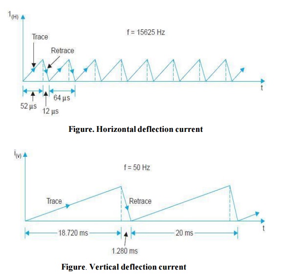
The wave
shapes of both horizontal and vertical sweep currents are shown in Fig. As
shown there the retrace times involved (both horizontal and vertical) are due
to physical limitations of practical scanning systems and are not utilized for
transmitting or receiving any video signal.
The
nominal duration of the horizontal line as shown in Fig. (a)is 64 μs (10 6
/15625 = 64 μs), out of which the active line period is 52 μs and the remaining
12 μs is the line blanking period. The beam returns during this short interval
to the extreme left side of the frame to start tracing the next line.
Similarly
with the field frequency set at 50 Hz, the nominal duration of the vertical
trace (see Fig (b)) is 20 ms (1/50 = 20 ms). Out of this period of 20 ms,
18.720 ms are spent in bringing the beam from top to bottom and the remaining
1.280 ms is taken by the beam to return back to the top to commence the next
cycle.
Since the
horizontal and vertical sweep oscillators operate continuously to achieve the
fast sequence of interlaced scanning, 20 horizontal lines F G 1280 μ s = 20
lines I J get traced during each vertical retrace interval.
Thus 40
scanning H 64 μ s K lines are lost per frame, as blanked lines during the
retrace interval of two fields. This leaves the active number of lines, Na ,
for scanning the picture details equal to 625 – 40 = 585, instead of the 625
lines actually scanned per frame. Scanning sequence.
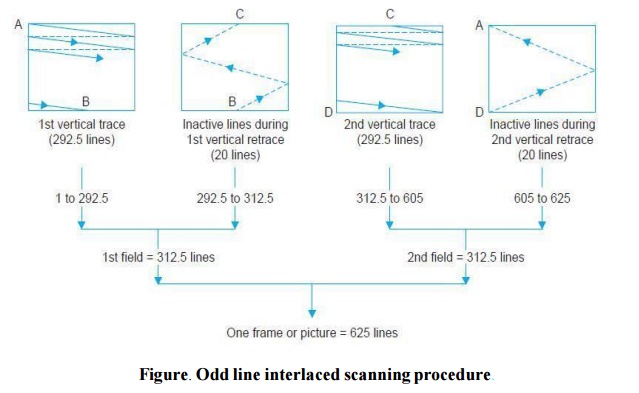
The
complete geometry of the standard interlaced scanning pattern is illustrated in
Fig. Note that the lines are numbered in the sequence in which these are
actually scanned. During the first vertical trace actually 292.5 lines are
scanned.
The beam
starts at A, and sweeps across the frame with uniform velocity to cover all the
picture elements in one horizontal line. At the end of this trace the beam then
retraces rapidly to the left side of the frame as shown by the dashed line in
the illustration to begin the next horizontal line.
Note that
the horizontal lines slope downwards in the direction of scanning because the
vertical deflecting current simultaneously produces a vertical scanning motion,
which is very slow compared with horizontal scanning. The slope of the
horizontal trace from left to right is greater than during retrace from right
to left.
The
reason is that the faster retrace does not allow the beam so much time to be
deflected vertically. After line one, the beam is at the left side ready to
scan line 3, omitting the second line.
However,
as mentioned earlier it is convenient to number the lines as they are scanned
and so the next scanned line skipping one line, is numbered two and not three.
This process continues till the last line gets scanned half when the vertical
motion reaches the bottom of the raster or frame.
As
explained earlier skipping of lines is accomplished by doubling the vertical
scanning frequency from the frame or picture repetition rate of 25 to the field
frequency of 50 Hz. With the field frequency of 50 Hz the height of the raster
is so set that 292.5 lines get scanned as the beam travels from top to bottom
and reaches point B.
Now the
retrace starts and takes a period equal to 20 horizontal line periods to reach
the top marked C.
These 20
lines are known as inactive lines, as the scanning beam is cut-off during this
period. Thus the second field starts at the middle of the raster and the first
line scanned is the 2nd half of line number 313.
The
scanning of second field, starting at the middle of the raster automatically
enables the beam to scan the alternative lines left un-scanned during the first
field. The vertical scanning motion otherwise is exactly the same as in the
previous field giving all the horizontal lines the same slope downwards in the
direction of scanning.
As a
result 292.5 lines again get scanned and the beam reaches the bottom of the
frame when it has completed full scanning of line number 605.
The
inactive vertical retrace again begins and brings the beam back to the top at
point A in a period during which 20 blanked horizontal lines (605 to 625) get
scanned. Back at point A, the scanning beam has just completed two fields or
one frame and is ready to start the third field covering the same area (no. of
lines) as scanned during the first field. This process (of scanning fields) is
continued at a fast rate of 50 times a second, which not only creates an
illusion of continuity but also solves the problem of flicker satisfactorily.
Related Topics