Chapter: Television and Video Engineering : Fundamentals of Television
Scanning Sequence Details
SCANNING SEQUENCE DETAILS
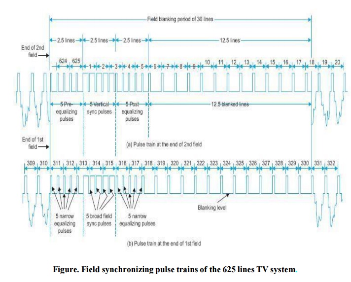
A complete chart giving line numbers and pulse designations for both the fields (corresponding to Fig) is given below :
First Field (odd field)
Line numbers : one to 1st-half of 313th line (312.5 lines)
1, 2 and 3rd 1st-half, lines 2.5 lines — Vertical sync pulses
3rd 2nd-half, 4, and 5 2.5 lines — Post-vertical sync equalizing pulses.
6 to 17, and 18th 1st-half 12.5 lines — blanking retrace pulses
18th 2nd-half to 310 292.5 lines — Picture details
311, 312, and 313th 1st-half 2.5 lines — Pre-vertical sync equalizing pulses for the 2nd field.
Total number of lines = 312.5
Second field (even field)
Line numbers : 313th 2nd-half to 625 (312.5 lines)
313th 2nd-half, 314, 315 2.5 lines — Vertical sync pulses
316, 317, 318th 1st-half 2.5 lines — Post-vertical sync equalizing pulses
318th 2nd-half-to 330 12.5 lines — Blanking retrace pulses
331 to 1st-half of 623rd 292.5 line — Picture details
623 2nd-half, 624 and 625 2.5 lines — Pre-vertical sync equalizing pulses for the
1st field
Total number of lines = 312.5
Total Number of Lines per Frame = 625
COMPOSITE VIDEO SIGNAL
Approximate location of line numbers. The serrated vertical sync pulse forces the vertical
deflection circuity to start the flyback. However, the flyback generall y does not begin with the start of vertical sync because the sync pulse must build up a minimum voltage across the capacitor to trigger the scanning oscillator.
If it is assumed that vertical flyback starts with the leading edge of the fourth serration, a time of 1.5 lines passes during vertical sync before vertical flyback starts. Also five equalizing pulses occur before vertical sync pulse train starts.
Then four lines (2.5 + 1.5 = 4) are blanked at the bottom of the pricture before vertical retrace begins. A typical vertical retrace time is five lines. Thus the remaining eleven (20
– (4 + 5) =11) lines are blanked at the top of the raster. These lines provide the sweep oscillator enough time to adjust to a linear rise for uniform pick-up and reproduction of the picture.
FUNCTIONS OF VERTICAL PULSE TRAIN
By serrating the vertical sync pulses and the providing pre- and post-equalizing
pulses the following basic requirements necessary for successful interlaced scanning are ensured.
(a) A suitable field sync pulse is derived for triggering the field oscillator.
(b) The line oscillator continues to receive triggering pulses at correct intervals while the process of initiation and completion of the field time-base stroke is going on.
(c) It becomes possible to insert vertical sync pulses at the end of a line after the 2nd field and at the middle of a line at the end of the 1st field without causing any interlace error.
(d) The vertical sync build up at the receiver has precisely the same shape and timing on odd and even fields.
PREFERENCE OF AM FOR PICTURE SIGNAL TRANSMISSION
At the VHF and UHF carrier frequencies there is a displacement in time between the direct and reflected signals. The distortion which arises due to interference between multiple signals is more objectionable in FM than AM because fhe frequency of the FM signal continuously changes.
If FM were used for picture transmission, the changing best frequency between the multiple paths, delayed with respect to each other, would produce a bar interference pattern in the image with a shimmering effect, since the bars continuously change as the beat frequency
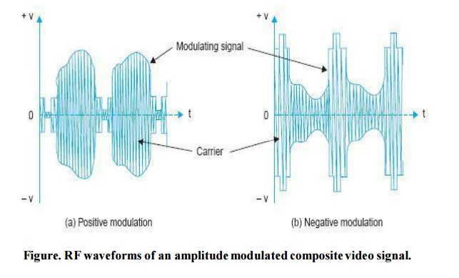
POSITIVE AND NEGATIVE MODULATION
When the intensity of picture brightness causes increase in amplitude of the modulated envelope,it is called ‘positive’ modulation.
When the polarity of modulating video signal is so chosen that sync tips lie at the 100 per cent level of carrier amplitude and increasing brightness produces decrease in the modulation envelope, it is called ‘negative modulation’.
The two polarities of modulation are illustrated in Fig
Comparison of Positive and Negative Modulation
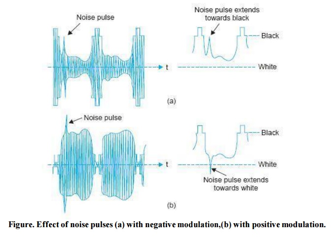
Effect of Noise Interference on Picture Signal. Noise pulses created by automobile ignition systems are most troublesome. The RF energy contained in such pulses is spread more or less uniformly over a wide frequency range and has a random distribution of phase and amplitude.
When such RF pulses are added to sidebands of the desired signal, and sum of signal and noise is demodulated, the demodulated video signal contains pulses corresponding to RF noise peaks, which extend principally in the direction of increasing envelope amplitude. This is shown in Fig.
Thus in negative system of modulation, noise pulse extends in black direction of the signal when they occur during the active scanning intervals. They extend in the direction of sync pulses when they occur during blanking intervals. In the positive system, the noise extends in the direction of the white during active scanning, i.e., in the opposite direction from the sync pulse during blanking.
Obviously the effect of noise on the picture itself is less pronounced when negative modulation is used. With positive modulation noise pulses will produce white blobs on the screen whereas in negative modulation the noise pulses would tend to produce black spots which are less noticeable against a grey background.
This merit of lesser noise interference on picture information with negative modulation has led to its use in most TV systems. (b) Effect of Noise Interference on Synchronization. Sync pulses with positive modulation being at a lesser level of the modulated carrier envelope are not much affected by noise pulses.
However, in the case of negativel y modulated signal, it is sync pulses which exist at maximum carrier amplitude, and the effect of interference is both to mutilate some of these, and to produce lot of spurious random pulses. This can completely upset the synchronization of the receiver time bases unless something is done about it.
Because of almost universal use of negative modulation, special horizontal stabilizing circuits have been developed for use in receivers to overcome the adverse effect of noise on synchronization. (c) Peak Power Available from the Transmitter. With positive modulation, signal corresponding to white has maximum carrier amplitude.
The RF modulator cannot be driven harder to extract more power because the non-linear distortion thus introduced would affect the amplitude scale of the picture signal and introduce brightness distortion in very bright areas of the picture.
In negative modulation, the transmitter may be over-modulated during the sync pulses without adverse effects, since the non-linear distortion thereby introduced, does not very much affect the shape of sync pulses. Consequently, the negative polarit y of modulation permits a large increase in peak power output and for a given setup in the final transmitter stage the output increases by about 40%. (d) Use of AGC (Automatic Gain Control) Circuits in the Receiver.
Most AGC circuits in receivers measure the peak level of the incoming carrier signal and adjust the gain of the RF and IF amplifiers accordingl y. To perform this measurement simply, a stable reference level must be available in the signal. In negative system of modulation, such a level is the peak of sync pulses which remains fixed at 100 per cent of signal amplitude and is not affected by picture details.
This level may be selected simply by passing the composite video signal through a peak detector. In the positive system of modulation the corresponding stable level is zero amplitude at the carrier and obviously zero is no reference, and it has no relation to the signal strength.
The maximum carrier amplitude in this case depends not onl y on the strength of the signal but also on the nature of picture modulation and hence cannot be utilized to develop true AGC voltage. Accordingly AGC circuits for positive modulation must select some other level (blanking level) and this being at low amplitude needs elaborate circuitry in the receiver.
Thus negative modulation has a definite advantage over positive modulation in this respect. The merits of negative modulation over positive modulation, so far as picture signal distortion and AGC voltage source are concerned, have led to the use of negative modulation in almost all TV systems now in use.
Related Topics