Chapter: Television and Video Engineering : Fundamentals of Television
Television Camera Tubes
TELEVISION CAMERA TUBES
A TV camera tube may be called the eye of a TV system. For such an analogy to be correct the tube must possess characteristic that are similar to its human counterpart. Some of the more important functions must be, sensitivity to visible light, (ii) wide dynamic range with respect to light intensity, and (iii) ability to resolve details while viewing a multi-element scene.
During the development of television, the limiting factor on the ultimate performance had always been the optical-electrical conversion device, i.e., the pick-up tube.
Most types developed have suffered to a greater or lesser extent from (i) poor sensitivity,
poor resolution, (iii) high noise level, (iv) undesirable spectral response, (v) instability, (vi) poor contrast range and (vii) difficulties of processing. However, development work during the past fifty years or so, has enabled scientists and engineers to develop image pick-up tubes, which not only meet the desired requirements but in fact excel the human eye in certain respects.
Such sensitive tubes have now been developed which deliver output even where our eyes see complete darkness. Spectral response has been so perfected, that pick-up outside the visible range (in infra-red and ultraviolet regions) has become possible. In fact, now there is a tube available for any special application.
BASIC PRINCIPLE
When minute details of a picture are taken into account, any picture appears to be composed of small elementary areas of light or shade, which are known as picture elements. The elements thus contain the visual image of the scene.
The purpose of a TV pick-up tube is to sense each element independently and develop a signal in electrical form proportional to the brightness of each element. As already explained in Chapter 1, light from the scene is focused on a photosensitive surface known as the image plate, and the optical image thus formed with a lens system represents light intensity variations of the scene.
The photoelectric properties of the image plate then convert different light intensities into corresponding electrical variations.
In addition to this photoelectric conversion whereby the optical information is transduced to electrical charge distribution on the photosensitive image plate, it is necessary to pick-up this information as fast as possible. Since simultaneous pick-up is not possible, scanning by an electron beam is resorted to.
The electron beam moves across the image plate line by line, and field by field to provide signal variations in a successive order. This scanning process divides the image into its basic picture elements. Through the entire image plate is photoelectric, its construction isolates the picture elements so that each discrete small area can produce its own signal variations.
Photoelectric Effects
The two photoelectric effects used for converting variations of light intensity into electrical variations are (i) photoemission and (ii) photoconductivity. Certain metals emit electrons when light falls on their surface.
These emitted electrons are called photoelectrons and the emitting surface a photocathode. Light consists of small bundles of energy called photons. When light is made incident on a photocathode, the photons give away their energy to the outer valence electrons to allow them to overcome the potential-energy barrier at the surface.
The number of electrons which can overcome the potential barrier and get emitted, depends on the light intensity. Alkali metals are used as photocathode because they have very low work-function.
Cesium-silver or bismuth-silver-cesium oxides are preferred as photo emissive surfaces because they are sensitive to incandescent light and have spectral response very close to the human eye. The second method of producing an electrical image is by photoconduction, where the conductivity or resistivity of the photosensitive surface varies in proportion to the intensity of light focused on it.
In general the semiconductor metals including selenium, tellurium and lead with their oxides have this property known as photoconductivity. The variations in resistance at each point across the surface of the material is utilized to develop a varying signal by scanning it uniformly with an electron beam. Image Storage Principle Television cameras developed during the initial stages of development were of the non-storage type, where the signal output from the camera for the light on each picture element is produced only at the instant it is scanned.
Most of the illumination is wasted. Since the effect of light on the image plate cannot be stored, any instantaneous pick-up has low sensitivity. Image di-sector and flying-spot camera are examples of non-storage type of tubes. These are no longer in use and will not be discussed.
High camera sensitivity is necessary to televise scenes at low light levels and to achieve this, storage t ype tubes have been developed. In storage type camera tubes the effect of illumination on every picture element is allowed to accumulate between the times it is scanned in successive frames. With light storage tubes the amount of photoelectric signal an be increased 10,000 times approximately compared with the earlier non-storage type.
The Electron Scanning Beam
As in the case of picture tubes an electron gun produces a narrow beam of electrons for scanning. In camera tubes magnetic focusing is normally employed. The electrons must be focused to a very narrow and thin beam because this is what determines the resolving capability of the camera.
The diameter of the beam determines the size of the smallest picture element and hence the finest detail of the scene to which it can be resolved. Any movement of electric charge is a flow of current and thus the electron beam constitutes a very small current which leaves the cathode in the electron gun and scans the target plate.
The scanning is done by deflecting the beam with the help of magnetic fields produced by horizontal and vertical coils in the deflection yoke put around the tubes. The beam
scans 312.5 lines per field and 50 such fields are scanned per second.
Video Signal
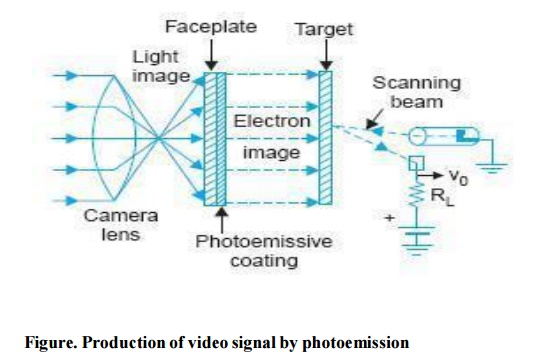
In tubes employing photo emissive target plates the electron beam deposits some charge on the target plate, which is proportional to the light intensity variations in the scene being televised.
The beam motion is so controlled by electric and magnetic fields, that it is decelerated before it reaches the target and lands on it with almost zero velocity to avoid any secondary emission.
Because of the negative acceleration the beam is made to move back from the target and on its return journey, which is very accurately controlled by the focusing and deflection coils, it strikes an electrode which is located very close to the cathode from where it started. The number of electrons in the returning beam will thus vary in accordance with the charge deposited on the target plate.
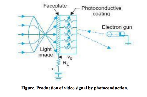
This in turn implies that the current which enters the collecting electrode varies in amplitude and represents brightness variations of the picture. This current is finally made to flow through a resistance and the varying voltage developed across this resistance constitutes the video signal. Figure (a) illustrates the essentials of this technique of developing video signal.In camera tubes employing photoconductive cathodes the scanning electron beam causes a flow of current through the photoconductive material.
The amplitude of this current varies in accordance with the resistance offered by the surface at different points. Since the conductivity of the material varies in accordance with the light falling on it, the magnitude of the current represents the brightness variations of the scene.
This varying current completes its path under the influence of an applied dc voltage through a load resistance connected in series with path of the current. The instantaneous voltage developed across the load resistance is the video signal which, after due amplification and processing is amplitude modulated and transmitted.
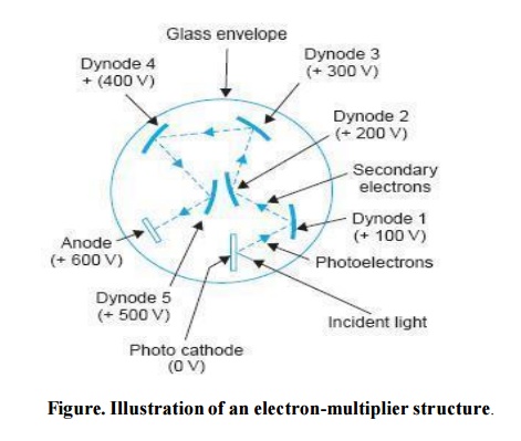
Figure (b) shows a simplified illustration of this method of developing video signal.Electron Multiplier When the surface of a metal is bombarded by incident electrons having high velocities, secondary emission takes place.
Aluminium, as an example, can release several secondary electrons for each incident primary electron. Camera tubes often include an electron multiplier structure, making use of the secondary emission effect to amplify the small amount of photoelectric current that is later employed to develop video signal.
The electron multiplier is a series of cold anode- cathode electrodes called dynodes mounted internally, with each at a progressively higher positive potential as illustrated in Fig. The few electrons emitted by the photocathode are accelerated to a more positive dynode.
The primary electrons can then force the ejection of secondary emission electrons when the velocity of the incident electrons is large enough. The secondary emission ratio is normally three or four, depending on the surface and the potential applied.
The number of electrons available is multiplied each time the secondary electrons strike the emitting surface of the next more positive dynode. The current amplification thus obtained is noise free because the electron multiplier does not have any active device or resistors.
Since the signal amplitude is very low any conventional amplifier, if used instead of the electron multiplier, would cause serious S/N ratio problems
Related Topics