Chapter: Embedded Systems Design : Basic peripherals
Parallel ports
Parallel ports
Parallel ports provide the ability to input or output binary data with a
single bit allocated to each pin within the port. They are called parallel
ports because the initial chips that provided this support grouped several pins
together to create a controllable data port similar to that used for data and
address buses. It transfers multiple bits of information simultaneously, hence
the name parallel port. Although the name implies that the pins are grouped
together, the individual bits and pins within the port can usually be used
independently of each other.
These ports are used to provide parallel interfaces such as the
Centronics printer interface, output signals to LEDs and alpha-numeric displays
and so on. As inputs, they can be used with switches and keyboards to support
control panels.
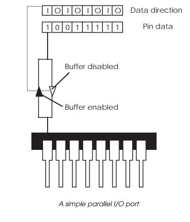
The basic operation is shown in the diagram which depicts an 8 pin port.
The port is controlled by two registers: a data direction register which
defines whether each pin is an output or an input and a data register which is
used to set an output value by writing to it and to obtain an input value by
reading from it. The actual implementation typically uses a couple of buffers
which are enabled depending on the setting of the corresponding bit in the data
direction register.
This simple model is the basis of many early parallel inter-face chips
such as the Intel 8255 and the Motorola 6821 devices. The model has progressed
with the incorporation of a third register or an individual control bit that
provides a third option of making the pin become high impedance and thus
neither an input or output. This can be implemented by switching off both
buffers and putting their connections to the pin in a high impedance state.
Output ports that can do this are often referred to as tri-state because they
can either be logic high, logic low or high impedance. In practice, this is
implemented on-chip as a single buffer with several control signals from the
appropriate bits within the control registers. This ability has led to the
development of general-purpose ports which can have additional functionality to
that of a simple binary input/output pin.
Multi-function I/O ports
With many parallel I/O devices that are available today, either as part
of the on-chip peripheral set or as an external device, the pins are described
as general-purpose and can be shared with other peripherals. For example, a pin
may be used as part of a serial port as a control signal.
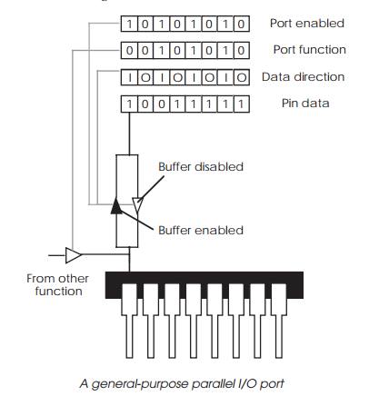
It may be used as a chip select for the memory design or simply as an I/O
pin. The function that the pin performs is set up internally through the use of
a function register which internally configures how the external pin is
connected internally. If this is not set up correctly, then despite the correct
programming of the other registers, the pin will not function as expected.
Note: This shared use does pose a problem for designers in that many manufacturer data sheets will specify the total number
of I/O pins that are available. In practice, this is often reduced because pins
need to be assigned as chip selects and to other essential functions. As a
result, the number that is available for use as I/O pins is greatly reduced.
Pull-up resistors
It is important to check if a parallel I/O port or pin expects an
external pull-up resistor. Some devices incorporate it internally and therefore
do not need it. If it is needed and not supplied, it can cause incorrect data
on reading the port and prevent the port from turning off an external device.
Related Topics