Chapter: Embedded Systems Design : Basic peripherals
8253 timer modes
8253 timer modes
A good example of a simple timer is the Intel 8253 which is used in the
IBM PC. The device has three timer/counters which provide a periodic ‘tick’ for
the system clock, a regular interrupt every 15 µs to
perform a dynamic memory refresh cycle and, finally, a source of square
waveforms for use as audio tones with the built-in speaker. Each timer/counter
supports six modes which cover most of the simple applications for
timer/counters.
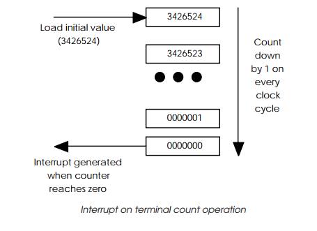
Interrupt on terminal count
This is known as mode 0 for the 8253 and is probably the simplest of its
operations to understand. An initial value is loaded into the counter register
and this then immediately starts to count down at the frequency determined by
the clock input. When the counter reaches zero, an interrupt is generated.
Programmable one-shot
With mode 1, it is possible to create a single pulse with a programmable
duration. The pulse length is first loaded into the counter. Nothing further
happens until the external gate signal is pulled high. This rising edge starts
the counter to count down towards zero and the counter output signal goes high
to start the external pulse. When the counter reaches zero, the counter output
goes low thus ending the pulse.
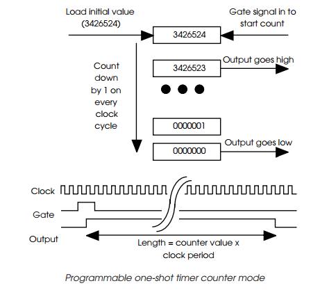
The pulse duration is determined by the initial value loaded into the
counter times the clock period. While this is a common timer/counter mode, many
devices such as the 8253 incorporate a reset. If the gate signal is pulled low
and then high again to create a new rising edge while the counter is counting
down, the current count value is ignored and replaced by the initial value and
the count continued. This means that the output pulse length will be extended
by the time between the two gate rising edges.
This mode can be used to provide pulse width modulation for power
control where the gate is connected to a zero crossing or similar detector or
clock source to create a periodic signal.
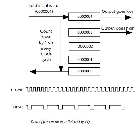
Rate generator
This is a simple divide by N
mode where N is defined by the
initial value loaded into the counter. The output from the counter consists of
a single low with the time period of a single clock followed by a high period
controlled by the counter which starts to count down. When the counter reaches
zero, the output is pulled low, the counter reloaded with the initial value and
the process repeated. This is mode 3 with the 8253.
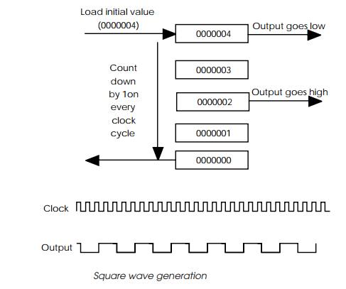
Square wave rate generator
Mode 4 is similar to mode 3 except that the waveform is a square wave
with a 50:50 mark/space ratio. This is achieved by extending the low period and
by reducing the high period to half the clock cycles specified by the initial
counter value.
Software triggered strobe
When mode 4 is enabled, the counter will start to count as soon as it is
loaded with its initial value. When it reaches zero, the output is pulsed low
for a single clock period and then goes high again. If the counter is reloaded
by software before it reaches zero, the output does not go low. This can be
used as a software-based watchdog timer where the output is connected to a
non-maskable interrupt line or a system reset.
Hardware triggered strobe
Mode 5 is similar to mode 4 except that the retriggering is done by the
external gate pin acting as a trigger signal.
Generating interrupts
The 8253 has no specific interrupt pins and therefore the timer OUT pin
is often used to generate an external interrupt signal. With the IBM PC, this
is done by connecting the OUT signal from timer/counter 0 to the IRQ 0 signal
and setting the timer/ counter to run in mode 3 to generate a square wave. The
input clock is 1.19318 MHz and by using a full 16 bit count value, is divided
by 65536 to provide a 18.3 Hz timer tick. This is counted by the software to
provide a time of day reference and to provide a system tick.
Related Topics