Chapter: Embedded Systems Design : Basic peripherals
Asynchronous flow control
Asynchronous flow control
Flow control is necessary to prevent either the terminal or the computer
from sending more data than the other can cope with. If too much is sent, it
either results in missing characters or in a data overrun error message. The
first flow control method is hardware handshaking, where hardware in the UART
detects a potential overrun and asserts a handshake line to tell the other UART
to stop transmitting. When the receiving device can take more data, the
handshake line is released. The problem with this is that there are several
options and, unless the lines are correctly connected, the handshaking does not
work correctly and data loss is possible. The second method uses software to
send flow control characters XON and XOFF. XOFF stops a data transfer and XON
restarts it. Unfortunately, there are many different ways of using these lines
and, as a result, this so-called standard has many different implementations.
There are alternative methods of ad-dressing this problem by adding buffers to
store data when it cannot be accepted.
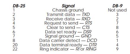
The two most common connectors are the 25 pin D type and the 9 pin D
type. These are often referred to as DB-25 and DB-9 respectively. Their pin
assignments are as follows:
There are many different methods of connecting these pins and this has
caused many problems especially for those faced with the task of implementing
the software for a UART in such a configuration. To implement hardware
handshaking, individual I/O pins are used to act as inputs or outputs for the
required signals. The functionality of the various signals is as follows:
TXD Transmit data. This transmits
data and would normally be connected to the RXD signal on the other side of the
connection.
RXD Receive data. This transmits
data and would normally be connected to the TXD signal on the other side of the
connection. In this way, there is a cross-over connection.
RTS Request to
send. This is used in conjunction with CTS to indicate that this side is ready to
send and needs confirmation that the other side is ready.
CTS Clear to
send. This is the corresponding signal to RTS and is sent by the other side on
receipt of the RTS to indicate that it is ready to receive data.
DSR Data set
ready. This is used in conjunction with DTR to indicate that each side is
powered on and ready.
DCD Data
carrier detect. This is normally used to determine which side is in control of
the hardware handshake protocol.
DTR Data
terminal ready. This is used in conjunction with DSR to indicate that each side
is powered on and ready.
RI Ring
indicator.This is asserted when a connected modem has detected an incoming
call.
Much of the functionality of these signals has been deter-mined by the
need to connect to modems initially to allow remote communication across
telephone lines. While modem links are still important, many serial lines are
used in modemless links to peripherals such as printers. In these cases, the
interchange of signals which the modem performs must be simulated within the
cabling and this is done using a null modem cable. The differences are best
shown by looking at some example serial port cables.
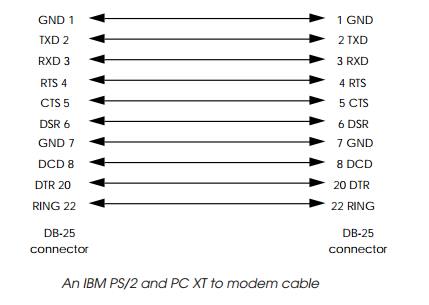
Modem cables
These are known as modem or straight through cables because the
connections are simply one to one with no crossing over or other more complex
wiring. They are used to link PCs with modems, printers, plotters and other
peripherals. However, do not use them when linking a PC to another PC or
computer — they won’t work! For those links, a null modem cable is needed.
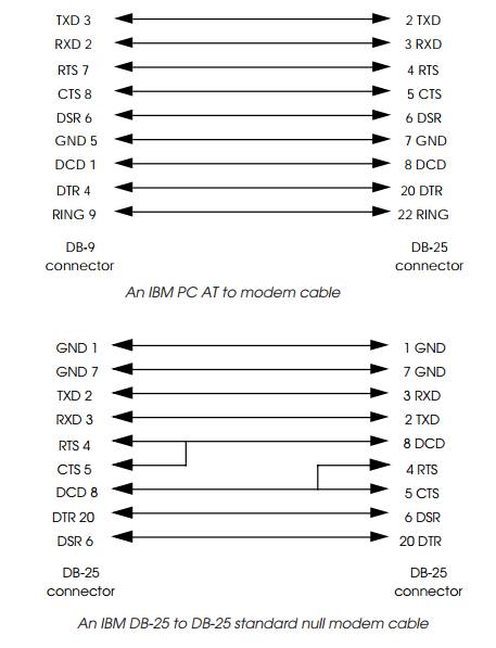
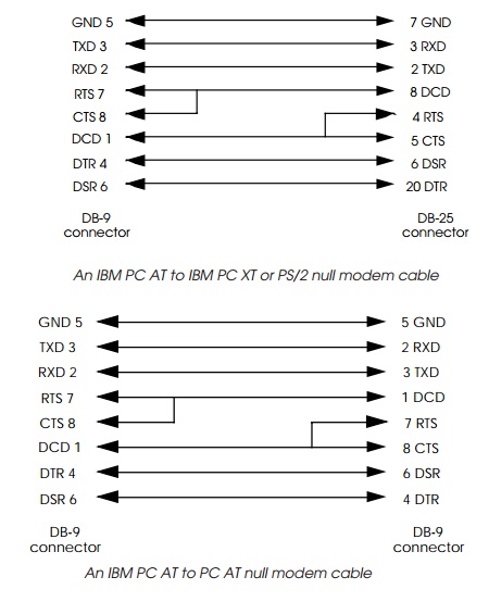
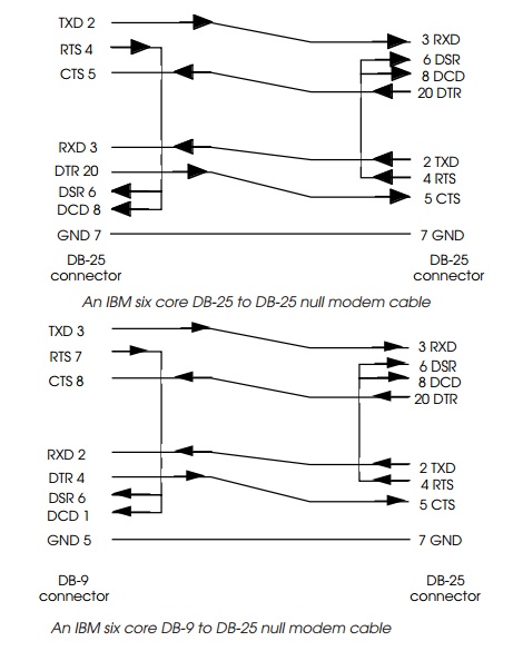
Null modem cables
Null modem cables are used to link PCs together. They work by switching
over the transmit and receive signals and the handshaking connections so that
each PC ‘sees’ a modem at the other end. There are many configurations
depending on the number of wires that are needed within the cable.
XON-XOFF flow control
Connecting these wires together and using the correct pins is not a
trivial job and two alternative approaches have been developed. The first is
the development of more intelligent UARTs that handle the flow control directly
with little or no intervention from the processor. The second is to dispense
with hardware handshaking completely and simply use software handshaking where
characters are sent to control the flow of characters between the two systems.
This latter approach is used by Apple Macintosh, UNIX and many other systems
because of its reduced complexity in terms of the hardware interface and
wiring.
With the XON-XOFF protocol, an XOFF character (control-S or ASCII code
13) is sent to the other side to tell it to stop sending any more data. The
halted side will wait until it receives an XON character (control-Q or ASCII
code 11) before recommencing the data transmission. This technique does assume
that each side can receive the XOFF character and that transmission can be
stopped before overflowing the other side’s buffer.
Related Topics