Chapter: Embedded Systems Design : Basic peripherals
A generic DMA controller
A generic DMA controller
A generic controller consists of several components which control the
operation:
•
Address generator
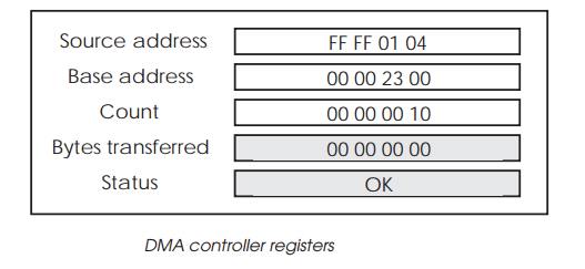
This is probably the most important part of a DMA control-ler and
typically consists of a base address register and an auto-incrementing counter
which increments the address after every transfer. The generated addresses are
used within the actual bus transfers to access memory and/or peripherals. When
a predefined number of bytes have been transferred, the base address is
reloaded and the count cleared to zero ready to repeat the operation.
•
Address bus
This is where the address created by the address generator is used to
access a specific memory location or peripheral.
•
Data bus
This is the data bus that is used to transfer data from the DMA
controller to the destination location. In some cases, the data transfer may be
made direct from the peripheral to the memory with the DMA controller directly
selecting the peripheral.
•
Bus requester
This is used to request the bus from the main CPU. In older designs, the
processor bus was not designed to support multiple masters and there were no
bus request signals. In these cases, the processor clock was extended or
delayed to steal memory cycles from the processor for the DMA con-troller to
use.
•
Local peripheral control
This allows the DMA controller to select the peripheral and get it to
accept or provide data directly or for a peripheral to request a data transfer,
depending on the DMA controller’s design. This is necessary to support the
single or implied address mode which is explained in more detail later on.
•
Interrupt signals
Most DMA controllers can interrupt the processor when the data transfers
are complete or if an error has occurred. This prompts the processor to either
reprogram the DMA control-ler for a different transfer or acts as a signal that
a new batch of data has been transferred and is ready for processing.
Operation
Using a DMA controller is reasonably simple provided the programming
defines exactly the data transfer operations that the processor expects. Most
errors lie in correct programming and in failing to understand how the device
operates. The key phases of its operation are:
•
Program the controller
Prior to using the DMA controller, it must be configured with parameters
that define the addressing such as base address and byte count that will be
used to transfer the data. In addition, the device will be configured in terms
of its communication with the processor and peripheral. Proces-sor
communication will normally include defining the con-ditions that will generate
an interrupt. The peripheral com-munication may include defining which request
pin is used by the peripheral and any arbitration mechanism that is used to
reconcile simultaneous requests for DMA from two or more peripherals. The final
part of this process is to define how the controller will transfer blocks of
data: all at once or individually or some other combination.
•
Start a transfer
A DMA transfer is normally initiated in response to a peripheral request
to start a transfer. It usually assumes that the controller has been correctly
configured to support this request. With a peripheral and processor, the
processor will normally request a service by asserting an interrupt pin which
is connected to the processor’s interrupt input(s). With a DMA controller, this
peripheral interrupt signal can be used to directly initiate a transfer or if
it is left attached to the processor, the interrupt service routine can start
the DMA transfers by writing to the controller.
•
Request the bus
The next stage is to request the bus from the processor. With most
modern processors supporting bus arbitration di-rectly, the DMA controller
issues a bus request signal to the processor which will release the bus when
convenient and allow the DMA controller to proceed. Without this support, the
DMA controller has to cycle steal from the processor so that it is held off the
bus while the DMA controller uses it. As will be described later on in this
chapter, most DMA controllers provide some flexibility concerning how they use
and compete with bus bandwidth with the processor and other bus masters.
•
Issue the address
Assuming the controller has the bus, it will then issue the bus to
activate the target memory location. A variety of interfaces are used — usually
dependent on the number of pins that are available and include both
non-multiplexed and multiplexed buses. In addition, the controller provides
other signals such as read/write and strobe signals that can be used to work
with the bus. DMA controllers tend to be designed for a specific processor
family bus but most recent devices are also generic enough to be used with
nearly any bus.
•
Transfer the data
The data is transferred either from a holding buffer within the DMA
controller or directly from a peripheral.
•
Update address generator
Once the data transfer has been completed, the address generator uses
the completion to calculate the address for the next transfer and update the
byte/transfer counters.
•
Update processor
Depending on how the DMA controller has been pro-grammed it can notify
the processor using interrupts of events within the transfer process such as an
address error or the completion of a data or block transfer.
Related Topics