Chapter: Embedded Systems Design : Basic peripherals
What is an RS232 serial port?
What is an RS232 serial port?
Up until now, the serial interfaces that have been described have used a
clock signal as a reference and therefore the data transfers are synchronous to
that clock. For the small distances between chips, this is fine and the TTL or
CMOS logic voltages are sufficient to ensure operation over the small
connection distances. However, this is not the case if the serial data is being
transmitted over many metres. The low voltage logic levels can be affected by
the cable capacitance and thus a logic one at the transmitter may be seen as an
indeterminate voltage at the receiver end. Clock edges can become skewed and
out of sync with the data causing the wrong data to be accepted. As a result, a
slightly different serial port is used for connecting over longer distances,
generically referred to an RS232.
For most people, the mention of RS232 immediately brings up the image
and experiences of connecting peripherals to the ubiquitous IBM PC. The IBM PC
typically has one or two serial ports, COM1
and COM2, which are used to transfer
data between the PC and printers, modems and even other computers. The term
‘serial’ comes from the fact that only one data line is used to transmit and
receive data and thus the information must be sent and received a bit at a
time. Instead of transmitting the 8 bits that make up a byte using eight data
lines at once, one data line is used to send 8 bits, one at a time. In
practice, several lines are used to provide separate lines for data transmit and
receive, and to pro-vide a control line for hardware handshaking. One important
difference is that the data is transmitted asynchronously i.e. there is no
separate reference clock. Instead the data itself provides its own reference
clock in terms of its format.
The serial interface can be divided into two areas. The first is the
physical interface, commonly referred to as RS232 or EIA232, which is used to
transfer data between the terminal and the computer. The electrical interface
uses a combination of +5, +12 and –12 volts for the electrical interface. This
used to require the provision of additional power connections but there are now
available interface chips that take a 5 volt supply (MC1489) and generate
internally the other voltages that are needed to meet the interface
specification. Typically, a logic one is signalled by a +3 to +15 volts level
and a logic zero by –3 to –15 volts. Many systems use +12 and –12 volts.
Note: The
term RS232 strictly specifies the physical inter-face and not the serial
protocol. Partly because RS232 is easier to say than universal asynchronous
commu-nication using an RS232 interface, the term has be-come a general
reference to almost any asynchro-nous serial communication.
The second area controls the flow of information between the terminal
and computer so that neither is swamped with data it cannot handle. Again,
failure to get this right can cause data corruption and other problems.
When a user presses a key, quite a lengthy procedure is carried out
before the character is transmitted. The pressed key generates a specific code
which represents the letter or other character. This is converted to a bit
pattern for transmission down the serial line via the serial port on the
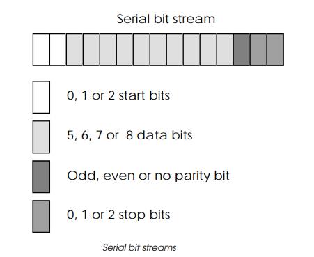
computer system. The converted bit pattern may contain a number of start bits,
a number of bits (5, 6, 7 or 8) representing the data, a parity bit for error
checking and a number of stop bits. These are all sent down the serial line by
a UART (universal asynchronous receiver transmit-ter) in the terminal at a
predetermined speed or baud rate.
The start bits are used to indicate that the data being transmitted is
the start of a character. The stop bits indicate that character has ended and
thus define the data sequence that con tains the data. The parity bit can
either be disabled, i.e. set to zero or configured to support odd or even
parity. The bit is set to indicate that the total number of bits that have been
sent is either an odd or even number. This allows the receiving UART to detect
a single bit error during transmission or reception. The bit sequencing and
resultant waveform is asynchronous in that there is not a reference clock
transmitted. The data is detected by using a local clock reference, i.e. from
the baud rate generator and the start/stop bit edges. This is why it is so
important not only to configure the data settings but to set the correct baud
rate settings so that the individual bits are correctly interpreted. As a
result, both the processor and the peripheral it is communicating with must use
the same baud rate and the same combination of start, stop, data and parity
bits to ensure correct communication. If different combinations are used, data
will be wrongly interpreted.
If the terminal UART is configured in half duplex mode, it echoes the
transmitted character so it can be seen on the screen. Once the data is
received at the other end, it is read in by another UART and, if this UART is
set up to echo the character, it sends it back to the terminal. (If both UARTs
are set up to echo, multiple characters are transmitted!) The character is then
passed to the application software or operating system for further processing.
If the other peripheral or processor is remote, the serial line may
include a modem link where the terminal is connected to a modem and a telephone
line, and a second modem is linked to the computer at the other end. The modem
is frequently controlled by the serial line, so if the terminal is switched
off, the modem effectively hangs up and disconnects the telephone line. Modems
can also echo characters and it is possible to get four characters on the
terminal screen in response to a single key stroke.
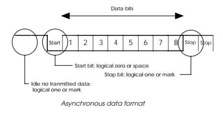
The actual data format for the sequence is shown in the diagram. When no
data is transmitted, the TXD signal is set to a logical one. When data is
transmitted, a start bit is sent by setting the line to a logical zero. Data is
then sent by setting the data to a zero or one accordingly and finally the stop
bits are sent by forcing the line to a logical one. The stop bits essentially
look the same as the idle bits when no data is being transmitted. The timing is
defined by the baud rate that both the receiver and transmitter are using. The
baud rate used to be supplied by an external timer/ counter called a baud rate
generator that generates a clock signal at the right frequency. This function
is now performed on-chip with modern controller chips and usually can work with
the system clock or with a simple watch crystal instead of one with a specific
frequency.
Note: If the
settings are slightly incorrect, i.e. the number of stop and data bits is
wrong, then it is possible for the data to appear to be received correctly. For
example, if data is transmitted at 7 data bits with 2 stop bits and received as
8 data bits with 1 stop bit, the receiver would get the 7 data bits and set the
eighth data bit to a one. If this character was then displayed on the screen,
it could appear in the correct format due to the fact that many character sets
ignore the eighth bit. In this case, the software and system would appear to
work. If the data was used in some other protocol where the eighth bit was
either used or assumed to be set to zero, the program and system would fail!
Related Topics