Chapter: Civil : Structural dynamics of earthquake engineering
Effective modal mass and modal height
Effective modal mass and modal height
The base shear for ŌĆśnŌĆÖ
mode is calculated as
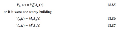
M n* is called
base shear modal mass or brevity effective modal mass. From that it is
clear that only the portion of Mn of the mass of a
multi-storey building is effective in producing base shear due to nth
mode because the building mass is distributed among various floor levels and
the equivalent static force mjŽĢjn varies
over the height. The sum of effective modal masses Mn over
the modes is equal to the mass of this building.
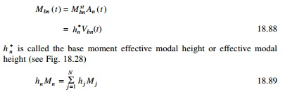
Example 18.11
Determine the effective modal
mass and the effective modal height for the frame shown in Fig. 18.29.
Solution
The modal distribution of
effective earthquake force is given in Fig. 18.30. Taking moment at base
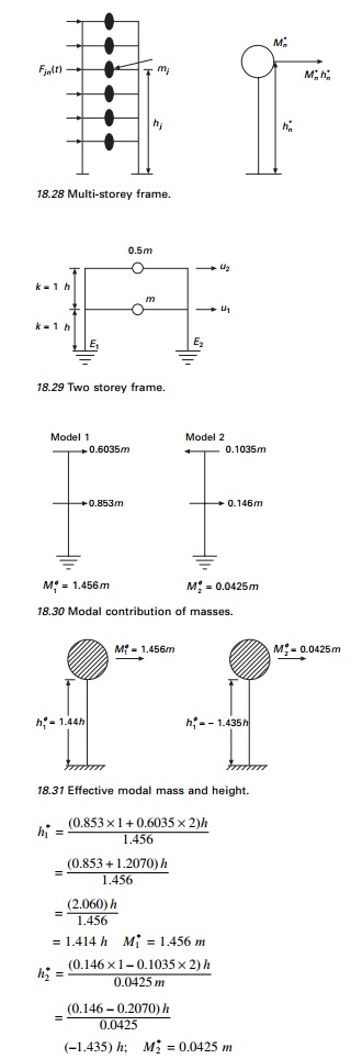
The effective modal mass and modal height are indicated in
Fig. 18.31.
Example 18.12
Consider a five storey building
(Example 18.1) (see Fig. 18.32) whose properties are given. Calculate effective
modal mass and height.
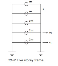
The effective modal mass and modal height are shown in Fig.
18.34.
The ground acceleration u˙˙g
(t ) is defined by its numerical value as time instant equally spaced at
Ōłåt. This
time step is chosen small enough to define u˙˙g (
t ) and to determine accurately the response of the SDOF system:
Base shear = m (7.0926A1(t) +
0.6471A2(t) + 0.2A3(t)
+ 0.0528A4(t)
+ 0.0003A5(t))
Base moment = mh (7.0927 ├Ś 3.079A1(t)
+ 0.6471 ├Ś (ŌĆō1.563)A2(t)
+ 0.2A3(t)
+ 0.0528 ├Ś (ŌĆō0.587)A4(t)
0.0003 ├Ś 7.67A5(t))
Multiple support excitation
There are certain examples in
which the ground motion generated by an earthquake is different from support to
support. For example the Golden Gate Bridge is 1965 m in length and the ground
motion is expected to vary significantly over the length of the base at the two
ends of the bridge.
Example18.13
A uniform two span continuous
bridge shown in Fig. 18.35 with flexural stiffness EI idealized as
lumped mass. Let us formulate the equation of motion subjected to vertical
motion at 1, 2, 3 as ug1, ug2,
ug3 at supports.
Formulation stiffness matrix 10 ├Ś 10. Assuming translational displacement as master and other
degrees of freedom as slaves we get reduced stiffness matrix of size 5 ├Ś 5.
Apply unit load at 3 (to get influence vector i1)
Moment at 4 = L
Calculate u2 when u3 = 1
The ŌĆō sign shown the deflection at 2 is downward.
Now calculate deflection at 1 due
to unit load at 3= deflection at 3 due to unit load at 1.
Apply unit load at 1
Both deflections at 3 and 1 are upwards and hence positive. If u3 = 1 let us calculate what is u1.
To find the influence vector i2,
apply unit load at 4 and find the deflection at 1 and 4. The deflection at 4
due to unit load at 4 is given by L3/6EI. If the load
is at a distance of ├Ś2 and the deflection is to
be calculated at ├Ś1, then deflection at ├Ś1 is given
When the deflection at 4 is equal
to 1 what is the deflection at 1 and 2 which may be calculated as
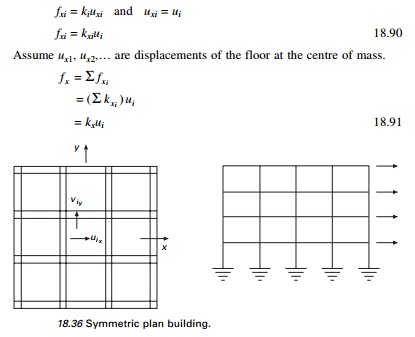
Symmetric plan
buildings: translational ground motion
Consider an N-storey
symmetric plan building having rigid floor displacement and several frames in
each x and y direction as shown in Fig. 18.36.
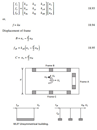
1 One storey, two way unsymmetric system
Consider the idealized one storey
frame shown in Fig. 18.37. Assume the diaphragm is rigid. Assume frame A
is located at a distance of e:
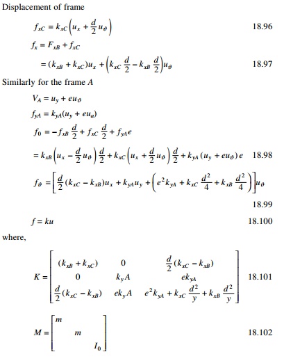
2 Equation of motion
Considering earthquake excitation defined by u˙˙gx
( t ), u╦Ö╦Ögy ( t ), u╦Ö╦Ög╬Ė ( t ) , we get the
equation of motion if (kxC = kxB)
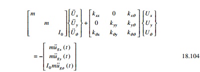
The above equations are coupled.
Thus the response of the system to x and y components of ground
motion is not restricted to lateral displacement x and y directions
but will also include lateral motions in tranverse directions and the
torsion of the roof diaphragm about the vertical axis.
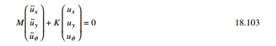
In Fig. 18.36, if frame A passes through the centre of
mass ŌĆśOŌĆÖ, then (e = 0) (kxB = kxC).
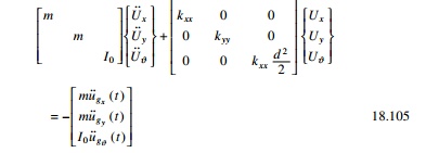
All three equations are uncoupled and solved.
Related Topics