Chapter: Civil : Structural dynamics of earthquake engineering
Approximate methods of analysis of multi-bay frames
Approximate
methods of analysis of multi-bay frames (lateral loads)
1 Portal method
(version 1)
This method was developed by
Robin Fleming (Norris and Wilbur,1960). The name is derived from the concept
which treats aisles of buildings as individual portals, as shown in Fig. 20.13.
The load P is transmitted
horizontally from portal, to portal giving rise to an independent overturning
effect in all of them. The leeward and windward columns of each portal are
subjected to compression and tension respectively. There is no direct stress in
the interior columns. This method is the most expeditious of all the various
methods of approximate analysis for wind and earthquake. In the absence of a
marked design dissymmetry, this method is effective up to 25 stories.
The following assumptions are made (Version 1):
The points of contra-flexure are at the mid-points of the
columns and girders.
The sum of all the earthquake loads above a given storey is
distributed as shear among the columns of that storey, in direct proportion to
the width of the aisles.
The bent resists all the earthquake load (with no help from
the walls, floors and partition). This assumption is common to all the methods.

Steps
1. Compute
the wind or earthquake loads. In a typical panel, load is the storey height
times the bay width times the unit wind or earthquake load. The roof load is
based on half the height of the top storey plus the parapet wall if any.
2. Distribute
the wind or earthquake load as shear among its columns in direct proportion to
the width of the aisles. In case of equal width aisles, the exterior columns of
the bent are assumed to take half as much shear as interior ones.
3. Compute
the moments in all the columns. Since the points of contra-flexure are assumed
to be at mid-storey height, the moments at the top and bottom will be equal to
the product of column shear and half the storey height.
4. Beginning
at the upper left corner of the bent and work towards the right and downward.
5. Find the
shear in the girders. The shear in the girder is equal to its end moment
divided by half of its span.
6. Find the
direct stress in the columns. This is done by taking out the joints one at a
time as free bodies and apply Ōłæ V
= 0.
7. Find the
direct stress in girders in the same free bodies used in step 6 and apply Ōłæ H = 0.
The free body diagram is shown in
Fig. 20.14 and the bending moment diagram in Fig. 20.15.
2 Portal method
version II
The assumptions are same as in Version I except that shear in
interior columns is twice the shear is exterior columns whatever the aisle
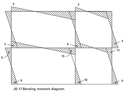
width. The free body
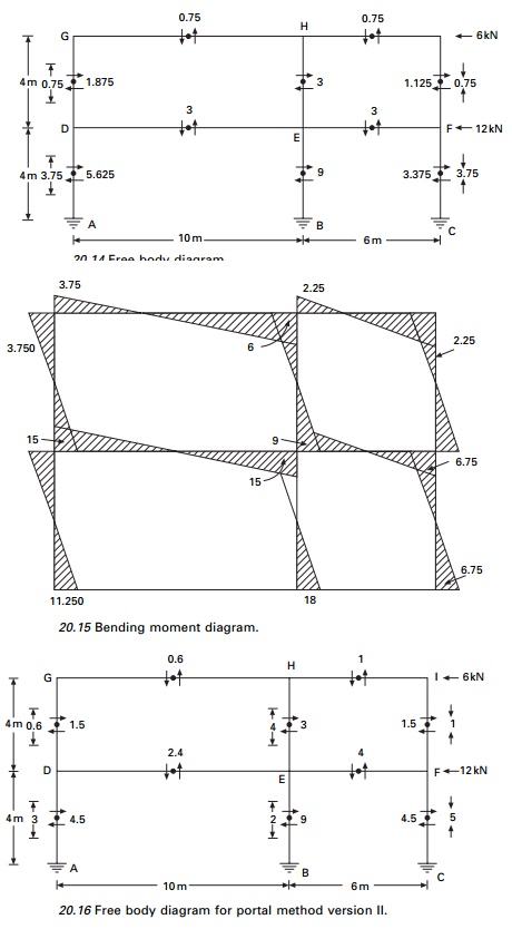
and bending moment diagrams (BMD)
are shown in Figs 20.16 and 20.17 respectively.
3 Cantilever
method ŌĆō Robin Fleming (1913)
The building is treated as a cantilever beam standing on end
and fixed to the ground. The beam formula thus applies and the columns become
chord members under an increasing direct stress from the neutral axis of the
building
outward. This method is effective
up to about 35 stories provided the height to width ratio is not greater than
four or five to one and provided the bents are not too much out of symmetry. It
must be assumed that in order to get cantilever action, the interior girders
must be sufficiently stiff to hold the floors in a plane under lateral
deflection from wind. This calls for a comparatively low lengthŌĆōdepth ratio for
the girders when shallow girderŌĆō column an earthquake wind connection is used.
The following assumptions are made:
1. The direct
stress in a column is directly proportional to its distance from the neutral axis of the bent.
2. The point of
contra-flexure in the girders is at mid-span.
3. The points of
contra-flexure of the columns are at mid-height.
Steps it
is usual to assume cross-sectional area of columns to be equal to 1:
1. Locate
the neutral axis of the bent by taking static moments of the column areas about
either external column.
2. Compute
the moment of inertia of the column areas.
3. Compute
the external wind shears and moments to be applied at each mid-story height and
record them.
4. Compute
direct stress in the exterior columns by f = My/I.
5. Beginning
at the upper left corner of the bent and working toward the
right and downward, find and record girder shears. This is
done by considering the free body and applying Ōłæ
V = 0.
6. Find and
record girder moments. They are equal to the product of girder shear times half
the span.
7. Find and
record column moments.
8. Find and
record beam moments.
The sum of the column shears across any storey should be equal
to the total external shear taken by that story. The free body and bending
moment diagrams are shown in Figs 20.18 and 20.19 respectively.
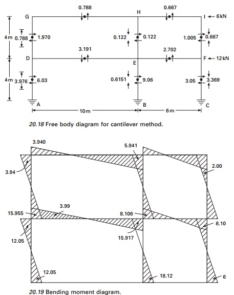
Taking the moment at A (see Fig. 20.18) we can find the
neutral axis as
Top storey
Moment at mid-height of top storey = 6 ’āŚ 2 = 12 kN m Taking
the moment about the neutral axis
k(1.332 + 7.342
+ 8.672) = 12; k = 0.091 Reaction in column GD =
0.091 ├Ś 8.67 = 0.788 Reaction in column HE = 1.34 ├Ś 8.67 = 0.122 Reaction in column IE = 7.34 ├Ś 8.67 = 0.667
Ground storey
Similarly taking moment at mid-height of bottom storey
k(1.332 + 7.342
+ 8.672) = 60; k = 0.4591 Reaction in DA = 0.451 ├Ś 8.67 = 3.976 Reaction in EB = 0.4591 ├Ś 1.34 = 0.6151 Reaction in CF = 0.4591 ├Ś 7.34 = 3.369
4 The factor
method
The factor method (Wilbur, 1934)
is another approximate method for analysing building frames subject to lateral
loads. This method is said to be more accurate than either the portal or the
cantilever method. In portal or cantilever methods, certain stress assumptions
are made so as to make the structure determinate. In this method the same
assumptions regarding the elastic action of the structure are made. These
assumptions enable an approximate slope deflection analysis of the bent to be
made.
In the previous methods, the
relative K values of the members do not enter into the calculations, but
this method takes the relative K-values of the members. To this extent,
the results of this method are more accurate than other methods.
Steps:
For each joint, compute the girder factor ŌĆśgŌĆÖ by using g
= Ōłæ Kc/Ōłæ K (as shown in Table 20.2) where Ōłæ Kc = sum of k
values of all columns meeting at the joint, Ōłæ
K = sum of k values of all members meeting at the joints. Write ŌĆśgŌĆÖ
values at the near end of each joint.
2. For each joint,
compute column factor ŌĆścŌĆÖ as c = 1 ŌĆō g; write c values at near end. For fixed
column bases of first storey take c = 1.
3. To each of these
members of c or g values add half of the number at the other end of the members.
4. Multiply each
sum from step 3, by the K values of the member concerned. For columns, call this factor the column
moment factor Cm; for girders call this factor the girder moment factor Gm.
5. The column
moment factors obtained from step 4 are actually approximate relative values for column end moments in
that storey. The sum of the column end moments in a storey is equal by statics
to the total horizontal shear of the storey multiplied by storey height. Hence
individual column moments may be
found.
6. Girder moment
factors Gm from step 4 are really relative end moment values for the girders at each joint. The sum of girder end
moments at each joint is equal to sum of column end moments at that joint.
Hence girder end moments can be worked out.
7. Knowing the end
moments of all members, other values such as girder shears, column shears and column axial forces and girder forces
can be worked out.
The calculations are shown in Figs 20.20 and 20.21 and the
bending moment diagram is shown in Fig. 20.22.
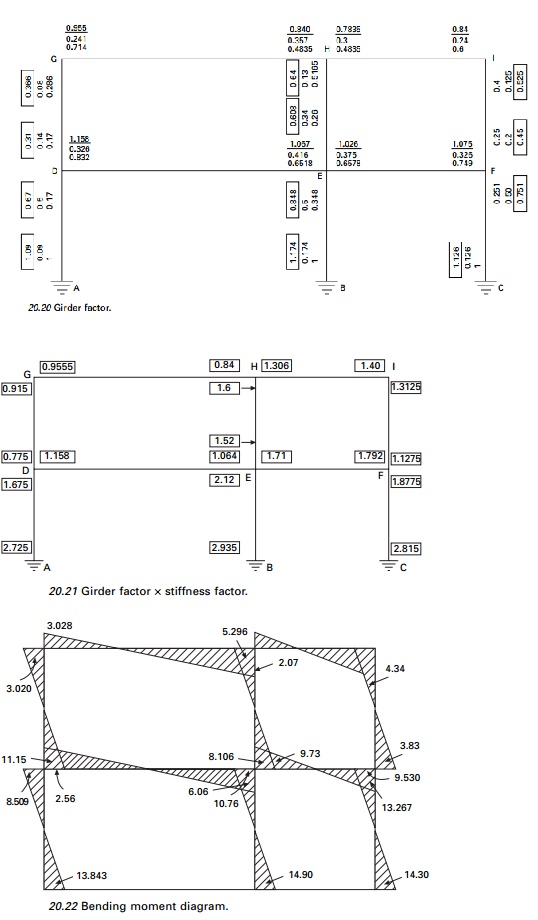
Assume stiffness of GH = I/10 = 1
Corresponding stiffness of HI = 1 ├Ś 10/6 = 1.667
Corresponding stiffness of DG = 1 ├Ś 10.4 = 2.5
Corresponding stiffness of AD =
2.5
Multiply the factors obtained by
stiffness factors; these values are given in Fig. 20.21.
Top storey column moments
A(0.915 +
0.775 + 1.6 + 1.52 + 1.3125 + 1.1275) = 24; A = 3.31
MGD = 3.31
├Ś 0.915 =
3.028
and similarly other moments are
calculated and the moment diagram is shown in Fig. 20.22.
4 The factor method
5 Stiffness centre
method
With the exception of the factor
method, the portal and cantilever methods both assume that there is a point of
inflexion at the mid-points of each girder and column when the building frame
is subjected to lateral loads (Kardestuncer, 1974a).
In the cantilever method the
magnitude of axial force in each column varies according to the distance of the
centre of gravity of all columns under consideration. When a system consists of
hollow portions or is made of beams and columns, due to rotations of girders
the plane sections no longer remain plane after the application of loads. Hence
the concept of centre of gravity in the cantilever method is a grossly wrong
assumption, although the factor method formulated by Wilbur has improved the
calculations considerably.
Steps:
1.
Calculate axial stiffness coefficients
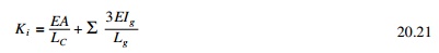
Quite
often, since the change in length of a member has very little effect it can be
omitted. The second term in this equation represents the summation of
transverse bending stiffness of girders attached to the column. Note that the
cantilever method omits the second term instead of the first (see Fig 20.23).
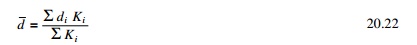
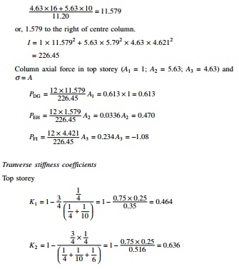
2. Locate the stiffness centre by
3. The axial force developed in each column due
to total moment of all forces above the mid-height of the storey under
consideration will be computed analogous to the axial stress distribution in a
cross-section, but having the neutral axis located at the stiffness centre.
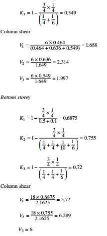
4. Calculate transverse stiffness coefficients as
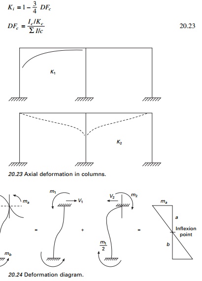
The
deformation diagram is shown in Fig. 20.24.
5. Distribute the wind shear according to the
transverse stiffness coefficients
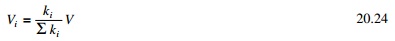
The above
equation explains why the interior columns of a storey with equal size of
columns carry larger transverse force than do the exterior columns. The ratio,
however, is never twice.
6. The inflexion point of a column may be located
as
For columns with a
fixed base, the inflexion point is between the mid-height and the top of the
column. Most often it is found to be located at 0.6LŌĆō0.7L from
the base rather than 0.5L. The inflexion point is higher in exterior columns
than in interior columns.
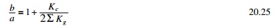
7.Calculate
moments and shears. Axial stiffness coefficients
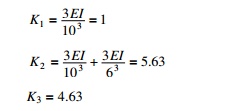
8.Calculate stiffness
centre
The inflexion point may be
assumed to be between 0.6 and 0.7L from base. Knowing the shear, the
column moment may be calculated. From the column moments beam moments may be
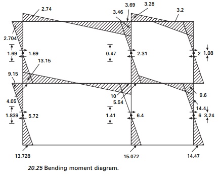
calculated. The bending moment diagram by the stiffness centre method is shown
in Fig. 20.25.
A
comparison of various methods is given in Table 20.3.
Analysis of
buildings simple in plan for lateral loads
The distribution of the load to
the VLLR elements depends on the stiffness and rigidity of the diaphragm. If
the diaphragm is rigid, the lateral force acting in a particular storey can be
distributed to the VLLR elements in proportion to their stiffness.
The
following assumptions are made:
1. All the
elements are connected by a rigid deck.
2. The axes
passes through centre of stiffness.
3. Forces
and distances are positive in the positive coordinate direction; rotations and
moments are positive in the anticlockwise direction.
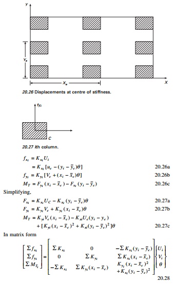
Let CS be the centre of
stiffness. The displacement at centre of stiffness may be defined as (see Fig.
20.26)
Displacement
of CS in x direction = UC
Displacement
of CS in y direction = VC
Angle of
rotation = ╬Ė
The
centre of stiffness can be determined as follows. Consider the ith
column (see Fig. 20.27)
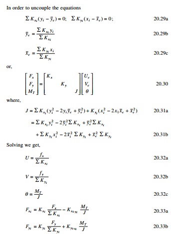
In the
case of an unsymmetric plan of the building, the resultant eccentric to and
acting at the centre of mass may be replaced by an equivalent load and a moment
ŌĆśMŌĆÖ acting at the centre of the stiffness. The forces acting on each
column may be denoted as in the x and y directions.
Related Topics