Chapter: Security in Computing : Security in Networks
Network Protocols
Protocols
When we use a network, the
communication media are usually transparent to us. That is, most of us do not
know whether our communication is carried over copper wire, optical fiber,
satellite, microwave, or some combination. In fact, the communication medium
may change from one transmission to the next. This ambiguity is actually a
positive feature of a network: its independence. That is, the communication is
separated from the actual medium of communication. Independence is possible
because we have defined protocols
that allow a user to view the network at a high, abstract level of
communication (viewing it in terms of user and data); the details of how the
communication is accomplished are hidden within software and hardware at both
ends. The software and hardware enable us to implement a network according to a
protocol stack, a layered
architecture for communications. Each layer in the stack is much like a
language for communicating information relevant at that layer.
Two popular protocol stacks
are used frequently for implementing networks: the Open Systems Interconnection
(OSI) and the Transmission Control
Protocol and Internet Protocol (TCP/IP) architecture. We examine each one in
turn.
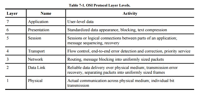
ISO OSI Reference Model
The International Standards Organization (ISO)
Open Systems Interconnection model consists of layers by which a network
communication occurs. The OSI reference model contains the seven layers listed
in Table 7-1.
How communication works across the different
layers is depicted in Figure 7-5. We can
think of the layers as creating an assembly line, in which each layer adds its
own service to the communication. In concert, the layers represent the
different activities that must be performed for actual transmission of a
message. Separately, each layer serves a purpose; equivalent layers perform
similar functions for the sender and receiver. For example, the sender's layer
four affixes a header to a message, designating the sender, the receiver, and
relevant sequence information. On the receiving end, layer four reads the
header to verify that the message is for the intended recipient, and then
removes this header.
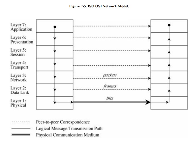
Each layer passes data in
three directions: above with a layer communicating more abstractly, parallel or
across to the same layer in another host, and below with a layer handling less
abstract (that is, more fundamental) data items. The communications above and
below are actual interactions, while the parallel one is a virtual
communication path. Parallel layers are called "peers."
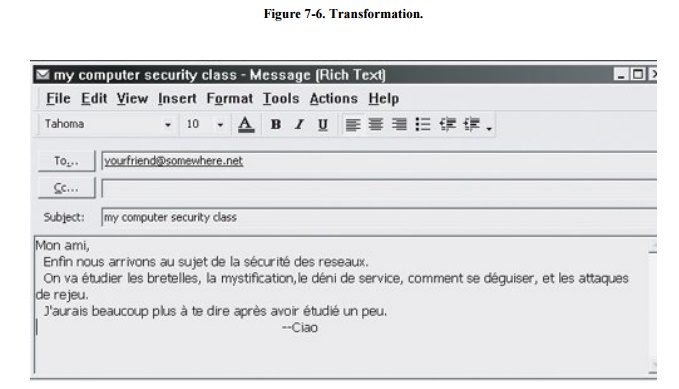
Let us look at a simple example of protocol
transmission. Suppose that, to send email to a friend, you run an application
such as Eudora, Outlook, or Unix mail. You type a message, using the
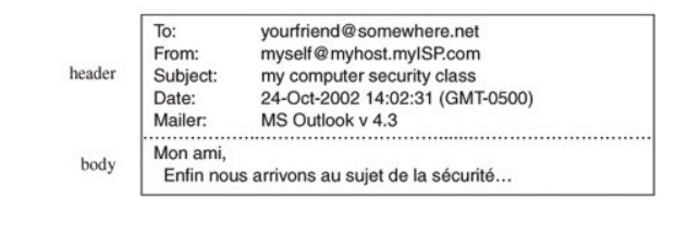
application's editor, and the application formats the message into two parts: a
header that shows to whom the message is intended (as well as other things,
such as sender and time sent), and a body that contains the text of your
message. The application reformats your message into a standard format so that
even if you and your friend use different mail applications, you can still
exchange e-mail. This transformation is shown in Figure
7-6.
However, the message is not
transmitted exactly as you typed it, as raw text. Raw text is a very
inefficient coding, because an alphabet uses relatively few of the 255 possible
characters for an 8-bit byte. Instead, the presentation layer is likely to
change the raw text into something else. It may do compression, character
conversions, and even some cryptography. An e-mail message is a one-way
transfer (from sender to receiver), so it is not initiating a session in which
data fly back and forth between the two endpoints. Because the notion of a
communication session is not directly relevant in this scenario, we ignore the
session layer for now. Occasionally, spurious signals intrude in a
communication channel, as when static rustles a telephone line or interference
intrudes on a radio or television signal. To address this, the transport layer
adds error detection and correction coding to filter out these spurious
signals.
Addressing
Suppose your message is addressed to
yourfriend@somewhere.net. This notation means that "somewhere.net" is
the name of a destination host (or more accurately, a destination network). At
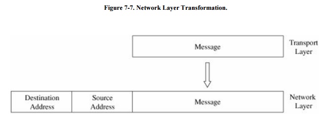
the network layer, a hardware device called a router actually sends the message from your network to a router on
the network somewhere.net. The network layer adds two headers to show your
computer's address as the source and somewhere.net's address as the
destination. Logically, your message is prepared to move from your machine to
your router to your friend's router to your friend's computer. (In fact,
between the two routers there may be many other routers in a path through the
networks from you to your friend.) Together, the network layer structured with
destination address, source address, and data is called a packet. The basic network layer protocol transformation is shown in
Figure 7-7.
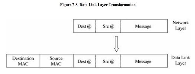
The message must travel from your computer to
your router. Every computer connected to a network has a network interface card (NIC) with a unique physical address, called
a MAC address (for Media Access
Control). At the data link level, two more headers are added, one for your
computer's NIC address (the source MAC) and one for your router's NIC address.
A data link layer structure with destination MAC, source MAC, and data is
called a frame. Every NIC selects
from the network those frames with its own address as a destination address. As
shown in Figure 7-8, the data link layer
adds the structure necessary for data to get from your computer to another
computer (a router is just a dedicated computer) on your network.
Finally, the message is ready
to be sent out as a string of bits. We noted earlier that analog transmissions
communicate bits by using voltage or tone changes, and digital transmissions
communicate them as discrete pulses. The physics and electronics of how bits
are actually sent are handled at the physical layer.
On the receiving
(destination) side, this process is exercised in reverse: Analog or digital
signals are converted to digital data. The NIC card receives frames destined
for it. The recipient network layer checks that the packet is really addressed
to it. Packets may not arrive in the order in which they were sent (because of
network delays or differences in paths through the network), so the session
layer may have to reorder packets. The presentation layer removes compression
and sets the appearance appropriate for the destination computer. Finally, the
application layer formats and delivers the data as an e-mail message to your
friend.
The layering and coordinating
are a lot of work, and each protocol layer does its own part. But the work is
worth the effort because the different layers are what enable Outlook running
on an IBM PC on an Ethernet network in Washington D.C. to communicate with a
user running Eudora on an Apple computer via a dial-up connection in Prague.
Moreover, the separation by layers helps the network staff troubleshoot when
something goes awry.
Layering
Each layer reformats the
transmissions and exchanges information with its peer layer. Let us summarize
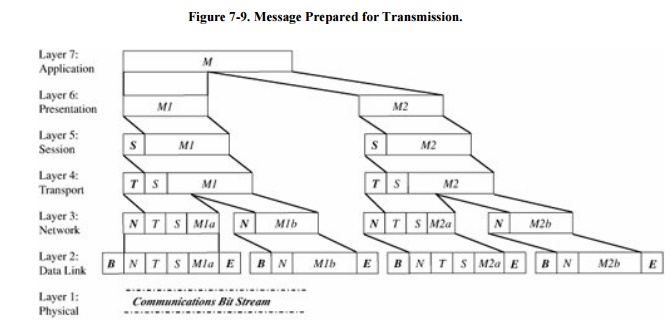
what each layer contributes. Figure 7-9 shows a typical message that has been acted upon by the
seven layers in preparation for transmission. Layer 6 breaks the original message data into blocks.
At the session layer (5), a session header is added to show the sender, the
receiver, and some sequencing information. Layer 4 adds information concerning
the logical connection between the sender and receiver. The network layer (3)
adds routing information and divides the message into units called packets, the
standard units of communication in a network. The data link layer (2) adds both
a header and a trailer to ensure correct sequencing of the message blocks and
to detect and correct transmission errors. The individual bits of the message
and the control information are transmitted on the physical medium by level 1.
All additions to the message are checked and removed by the corresponding layer
on the receiving side.
The OSI model is one of
several transmission models. Different network designers implement network
activities in slightly different combinations, although there is always a clear
delineation of responsibility. Some designers argue that the OSI model is
overly complexit has too many levelsand so other models are typically shorter.
TCP/IP
The OSI model is a conceptual
one; it shows the different activities required for sending a communication.
However, full implementation of a seven-layer transmission carries too much
overhead for megabit-per-second communications; the OSI protocol slows things
down to unacceptable levels. For this reason, TCP/IP (Transmission Control
Protocol/Internet Protocol) is the protocol stack used for most wide area
network communications. TCP/IP was invented for what became the Internet.
TCP/IP is defined by protocols, not layers, but we can think of it in terms of
four layers: application, host-to-host (end-to-end) transport, Internet, and
physical. In particular, an application program deals only with abstract data
items meaningful to the application user. Although TCP/IP is often used as a
single acronym, it really denotes two different protocols: TCP implements a connected communications session on top of the
more basic IP transport protocol. In
fact, a third protocol, UDP (user
datagram protocol) is also an essential part of the suite.
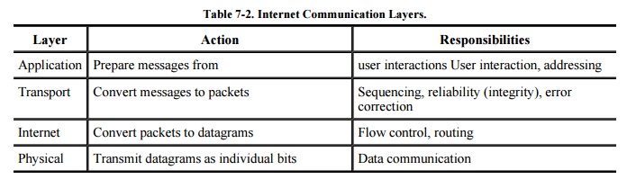
The transport layer receives variable-length messages from the
application layer; the transport layer breaks them down into units of
manageable size, transferred in packets. The Internet layer transmits
application layer packets in datagrams, passing them to different physical
connections based on the data's destination (provided in an address
accompanying the data). The physical layer consists of device drivers to perform
the actual bit-by-bit data communication. Table 7-2
shows how each layer contributes to the complete interaction.
The TCP protocol must ensure
the correct sequencing of packets as well as the integrity (correct
transmission) of data within packets. The protocol will put out-of-sequence
packets in proper order, call for retransmitting a missing packet, and obtain a
fresh copy of a damaged packet. In this way, TCP hands a stream of correct data
in proper order to the invoking application. But this service comes at a price.
Recording and checking sequence numbers, verifying integrity checks, and
requesting and waiting for retransmissions of faulty or missing packets take
time and induce overhead. Most applications expect a flawless stream of bits,
but some applications can tolerate a less accurate stream of data if speed or
efficiency is critical.
A TCP packet is a data
structure that includes a sequence number, an acknowledgment number for
connecting the packets of a communication session, flags, and source and
destination port numbers. A port is
a number designating a particular application running on a computer. For
example, if Jose and Walter begin a communication, they establish a unique
channel number by which their computers can route their respective packets to
each of them. The channel number is called a port. Each service uses a
well-known port, such as port 80 for HTTP (web pages), 23 for Telnet (remote
terminal connection), 25 for SMTP (e-mail), or 161 for SNMP (network management).
More precisely, each of these services has a waiting process that monitors the
specified port number and tries to perform its service on any data passed to
the port.
The UDP protocol does not
provide the error-checking and correcting features of TCP, but it is a much
smaller, faster protocol. For instance, a UDP datagram adds 8 bytes for control
information, whereas the more complex TCP packet adds at least 24 bytes.
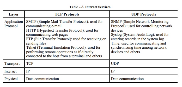
Most applications do not interact directly in
TCP or UDP themselves. Instead, they operate on data structured by an
application-level protocol applied on top of TCP or UDP. Some of the more
common Internet protocols are shown in Table 7-3.
Whatever the model, a layer
will typically subdivide data it receives from a higher layer and then add
header and/or trailer information to the data before passing it to a lower
layer. Each layer encapsulates the higher layer, so that higher layer headers
and trailers are seen simply as part of the data to be transmitted.
Addressing Scheme
For communication to occur,
the bits have to be directed to somewhere. All networks use an addressing
scheme so that data can be directed to the expected recipient. Because it is
the most common, we use the Internet addressing scheme known as IP addresses in
our examples, since it is the addressing handled by the IP protocol.
All network models implement an addressing
scheme. An address is a unique identifier for a single point in the network.
For obvious reasons, addressing in shared, wide area networks follows
established rules, while addressing in local area networks is less constrained.
Starting at the local area
network, each node has a unique address, defined in hardware on the network
connector device (such as a network interface card) or its software driver. A
network administrator may choose network addresses to be easy to work with,
such as 1001, 1002, 1003 for nodes on one LAN, and 2001, 2002, and so forth on
another.
A host on a TCP/IP wide area
network has a 32-bit address, called an IP
address . An IP address is expressed as four 8-bit groups in decimal
notation, separated by periods, such as 100.24.48.6. People prefer speaking in
words or pseudowords, so network addresses are also known by domain names, such as ATT.COM or
CAM.AC.UK. Addressing tables convert domain names to IP addresses.
A domain name is parsed from right to left. The
rightmost portion, such as .COM, .EDU, .NET, .ORG, or .GOV, or one of the
two-letter country specific codes, such as .UK, .FR, .JP, or .DE, is called a top-level domain. A small set of
organizations called the Internet Registrars controls these top-level domains;
the registrars also control the registration of second-level domains, such as
ATT in ATT.COM. Essentially, the registrars publish addresses of hosts that
maintain tables of the second-level domains contained in the top-level domain.
A host connected to the Internet queries one of these tables to find the
numeric IP address of ATT in the .COM domain. AT&T, the company owning the
ATT Internet site, must maintain its own host to resolve addresses within its
own domain, such as MAIL.ATT.COM. You may find that the first time you try to
resolve a fully qualified domain name to its IP address, your system performs a
lookup starting at the top; for subsequent attempts, your system maintains a
cache of domain name records that lets it resolve addresses locally. Finally, a
domain name is translated into a 32- bit, four -octet address, and that address
is included in the IP packets destined for that address. (We return to name
resolution later in this chapter because it can be used in network attacks.)
Routing Concepts
A host needs to know how to direct a packet
from its own IP address. Each host knows to what other hosts it is directly
connected, and hosts communicate their connections to their neighbors. For the
example network of Figure 7-2, System 1
would inform System 2 that it was one hop away from Clients A, B, and C. In
turn, System 2 would inform its other neighbor, System 3, that it (System 2)
was two hops away from Clients A, B, and C. From System 3, System 2 would learn
that System 3 was one hop away from Clients D and E, Server F, and System 4,
which System 2 would then pass to System 1 as being a distance of two hops. The
routing protocols are actually more complex than this description, but the
concepts are the same; hosts advertise to their neighbors to describe to which
hosts (addresses) they can route traffic and at what cost (number of hops).
Each host routes traffic to a neighbor that offers a path at the cheapest cost.
Related Topics