Optics | Physics - Thin Lens | 12th Physics : UNIT 6 : Ray Optics
Chapter: 12th Physics : UNIT 6 : Ray Optics
Thin Lens
THIN LENS
A lens is formed by a transparent material bounded between two spherical surfaces or one plane and another spherical surface. In a thin lens, the distance between the surfaces is very small. If there are two spherical surfaces, then there will be two centres of curvature C1 and C2 and correspondingly two radii of curvature R1 and R2. A plane surface has its center of curvature C at infinity and its radius of curvature R is infinity (R = ∞).
The terminologies of spherical mirrors also hold good very much for thin lens except for focal length.
Primary and secondary focal points
As the thin lens is formed by two spherical surfaces, the lens may separate two different media. i.e. the media to the left and right of the lens may be different. Hence, we have two focal lengths.
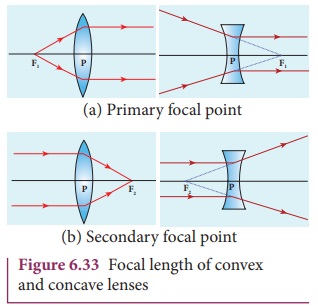
The primary focus F1 is defined as a point where an object should be placed to give parallel emergent rays to the principal axis as shown in Figure 6.33(a). For a convergent lens, such an object is a real object and for a divergent lens, it is a virtual object. The distance PF1 is the primary focal length f1.
The secondary focus F2 is defined as a point where all the parallel rays travelling close to the principal axis converge to form an image on the principal axis as shown in Figure 6.33(b). For a convergent lens, such an image is a real image and for a divergent lens, it is a virtual image. The distance PF2 is the secondary focal length f2.
If the media on the two sides of a thin lens have same refractive index, then the two focal lengths are equal. We will mostly be using the secondary focus F2 in our further discussions.
Sign conventions for lens on focal length
The sign conventions for thin lenses differ only in the signs followed for focal lengths.
(a) The sign of focal length is not decided on the direction of measurement of the focal length from the pole of the lens as they have two focal lengths, one to the left and another to the right (primary and secondary focal lengths on either side of the lens).
(b) The focal length of the thin lens is taken as positive for a converging lens and negative for a diverging lens.
The other sign conventions for object distance, image distance, radius of curvature, object height and image height (except for the focal lengths as mentioned above) remain the same for thin lenses as that of spherical mirrors.
Lens maker’s formula and lens equation
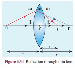
Let us consider a thin lens made up of a medium of refractive index n2 is placed in a medium of refractive index n1. Let R1 and R2 be the radii of curvature of two spherical ![]() surfaces
surfaces ![]() and
and ![]() respectively and P be the pole as shown in figure 6.34. Consider a point object O on the principal axis. The ray which falls very close to P, after refraction at the surface
respectively and P be the pole as shown in figure 6.34. Consider a point object O on the principal axis. The ray which falls very close to P, after refraction at the surface ![]() forms image at I'. Before it does so, it is again refracted by the surface
forms image at I'. Before it does so, it is again refracted by the surface ![]() . Therefore the final image is formed at I.
. Therefore the final image is formed at I.
The general equation for the refraction at a spherical surface is given from Equation (6.59),
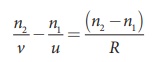
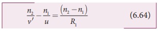
For the refracting surface ![]() , the light goes from n1 to n2.
, the light goes from n1 to n2.
For the refracting surface ![]() , the light goes from medium n2 to n1.
, the light goes from medium n2 to n1.
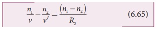
Adding the above two equations (6.64) and (6.65)
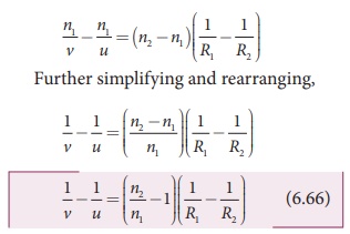
If the object is at infinity, the image is formed at the focus of the lens. Thus, for u = ∞, v = f. Then the equation becomes.
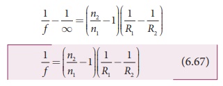
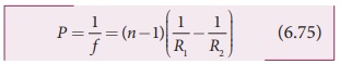
If the refractive index of the lens is n2 and it is placed in air, then n2 = n and n1 = 1. So the equation (6.67) becomes,
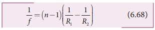
The above equation is called the lens maker’s formula, because it tells the lens manufactures what curvature is needed to make a lens of desired focal length with a material of particular refractive index. This formula holds good also for a concave lens. By comparing the equations (6.66) and (6.67) we can write,
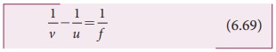
This equation is known as lens equation which relates the object distance u and image distance v with the focal length f of the lens. This formula holds good for a any type of lens.
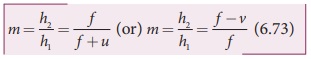
Lateral magnification in thins lens
Let us consider an object OO' of height h1 placed on the principal axis with its height perpendicular to the principal axis as shown in Figure 6.35. The ray OP passing through the pole of the lens goes undeviated. The inverted real image II ‘ formed has a height h2.
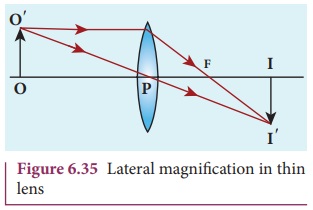
The lateral or transverse magnification m is defined as the ratio of the height of the image to that of the object.

From the two similar triangles ∆POO’ and ∆ PII ‘ , we can write,
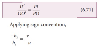
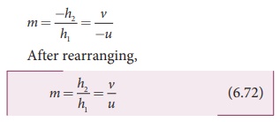
Substituting this in the equation (6.70) for magnification,
The magnification is negative for real image and positive for virtual image. In the case of a concave lens, the magnification is always positive and less than one.
We can also have the equations for magnification by combining the lens equation with the formula for magnification as,
EXAMPLE 6.14
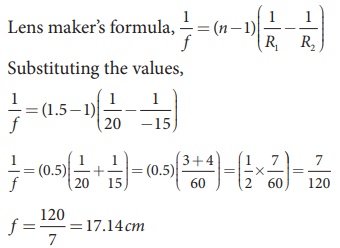
A biconvex lens has radii of curvature 20 cm and 15 cm each. The refractive index of the material of the lens is 1.5. What is its focal length? Will the focal length change if the lens is flipped by the side?
Solution
For a biconvex lens, radius of curvature of the first surface is positive and that of the second surface is negative side as shown in the figure.
Given, n = 1.5, R1=20 cm and R2= –15 cm
As the focal length is positive the lens is a converging lens.
If the lens is flipped back to front,
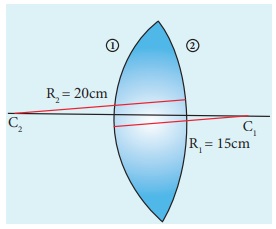
Now, R1= 15 cm and R2= –20 cm, n = 1.5 Substituting the values,
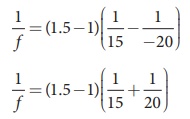
This will also result in, f = 17.14 cm
Thus, it is concluded that the focal length of the lens will not change if it is flipped side wise. This is true for any lens. Students can verify this for any lens.
EXAMPLE 6.15
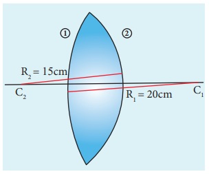
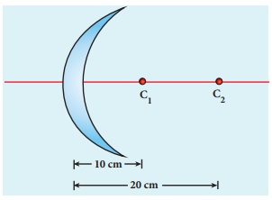
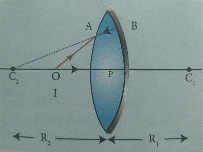
Determine the focal length of the lens made up of a material of refractive index 1.52 as shown in the diagram. (Points C1 and C2 are the centers of curvature of the first and second surface.)
Solution
This lens is called convexo-concave lens
Given, n = 1.52, R1= 10 cm and R2= 20 cm
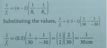
Lens makers formula,
1/ f = (n −1)( 1/R1 – 1/R2 ) Substituting the values,
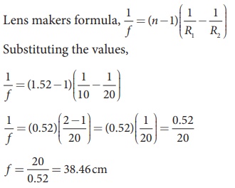
As the focal length is positive, the lens is a converging lens.
Power of a lens
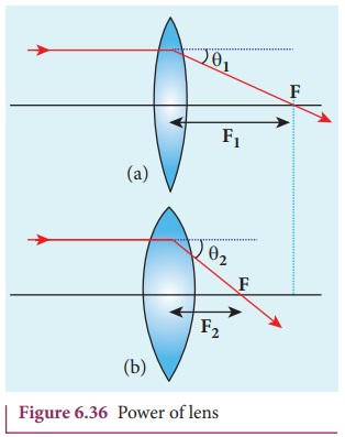
Power of lens is the measurement of deviating strength of a lens i.e. when a ray is incident on a lens then the degree with which the lens deviates the ray is determined by the power of the lens. Power of the lens is inversely proportional to focal length i.e. greater the power of lens, greater will be the deviation of ray and smaller will be the focal length. In Figure 6.36, the lens (b) has greater deviating strength than that of (a). As (b) has greater deviating strength, its focal length is less and vice versa.
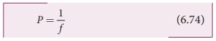
In other words, the power of a lens is a measure of the degree of convergence or divergence of light falling on it. The power of a lens P is defined as the reciprocal of its focal length.
The unit of power is diopter D. 1 D = 1 m–1. Power is positive for converging lens and negative for diverging lens.
From the lens makers formula, equation (6.68), the equation for power can be written as,
The outcome of this equation of power is that larger the value of refractive index, greater is the power of lens and vice versa. Also for lenses with small radius of curvature (bulky) the power is large and for lenses with large the radius of curvature (skinny), the power is small.
EXAMPLE 6.16
If the focal length is 150 cm for a glass lens, what is the power of the lens?
Solution
Given, focal length, f = 150 cm (or) f = 1.5 m
Equation for power of lens is, P = 1/f
Substituting the values,
P = 1/1.5 = 0.67diopter
As the power is positive, it is a converging lens.
Focal length of lenses in contact
Let us consider two lenses ![]() and
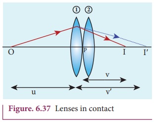
and ![]() of focal length f1 and f2 are placed coaxially in contact with each other so that they have a common principal axis. For an object placed at O beyond the focus of the first lens
of focal length f1 and f2 are placed coaxially in contact with each other so that they have a common principal axis. For an object placed at O beyond the focus of the first lens ![]() on the principal axis, an image is formed by it at I'. This image I' acts as an object for the second lens
on the principal axis, an image is formed by it at I'. This image I' acts as an object for the second lens ![]() and the final image is formed at I as shown in Figure. 6.37. As these two lenses are thin, the measurements are done with respect to the common optical centre P in the middle of the two lenses.
and the final image is formed at I as shown in Figure. 6.37. As these two lenses are thin, the measurements are done with respect to the common optical centre P in the middle of the two lenses.
Let, PO be object distance u and PI' be the image distance (v’) for the first lens ![]() and object distance for the second lens
and object distance for the second lens ![]() and PI = v be the image distance for the second lens
and PI = v be the image distance for the second lens ![]() .
.
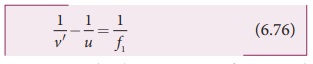
Writing the lens equation for first lens ![]() ,
,
Writing the lens equation for second lens ![]() ,
,
Adding the above two equations (6.76) and (6.77),
If the combination acts as a single lens of focal length f so that for an object at the position O it forms the image at I then,
Comparing equations (6.78) and (6.79) we can write,
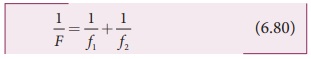
The above equation can be extended for any number of lenses in contact as,
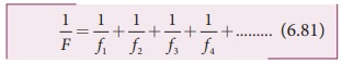
The above equation can be written as power of the lenses as,

Where, P is the net power of the lens combination of lenses in contact. One should note that the sum in equation (6.82) is an algebraic sum. The powers of individual lenses may be positive (for convex lenses) or negative (for concave lenses). Combination of lenses helps to obtain diverging or converging lenses of desired magnification. Also, combination of lenses enhances the sharpness of the images. As the image formed by the first lens becomes the object for the second and so on, the total magnification m of the combination is a product of magnification of individual lenses. We can write, m = m1 × m2 × m3 (without proof).
EXAMPLE 6.17
What is the focal length of the combination if a lens of focal length –70 cm is brought in contact with a lens of focal length 150 cm? What is the power of the combination?
Solution
Given, focal length of first lens, f1 = –70 cm, focal length of second lens, f2 = 150 cm.
Equation for focal length of lenses in contact, 1/F = 1/f1 + 1/f2
Substituting the values,
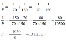
As the focal length is negative, the combination of two lenses is a diverging system of lenses.
The power of combination is,
P = 1/F = 1/-1.3125m = 0.76 diopter
Focal length of lenses in out of contact
When two thin lenses are separated by a distance d common optical center cannot be chosen for them. Hence, they cannot be treated as a single thin lens. Actually, such a combination should be treated as a thick lens for which the theory is more involved (beyond the scope of present study). However, as a special case, only when the object is placed at infinity, the combination can be replaced by a single thin lens. The focal length and position of the equivalent lens can be derived by considering the concept of angle of deviation.
Let O be a point object on the principal axis of a lens as shown in Figure 6.38. OA is the incident ray on the lens at a point A at a height h above the optical centre. The ray is deviated through an angle δ and forms the image at I on the principal axis.
The incident and refracted rays subtend the angles, ∠AOP = α and ∠AIP = β with the principal axis respectively.
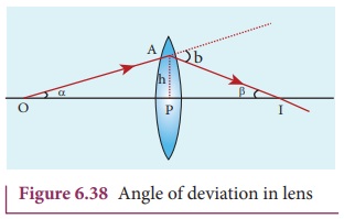
In the triangle ∆OAI, the angle of deviation δ can be written as,

If the height h is small as compared to PO and PI, the angles α, β and δ are also small. Then,
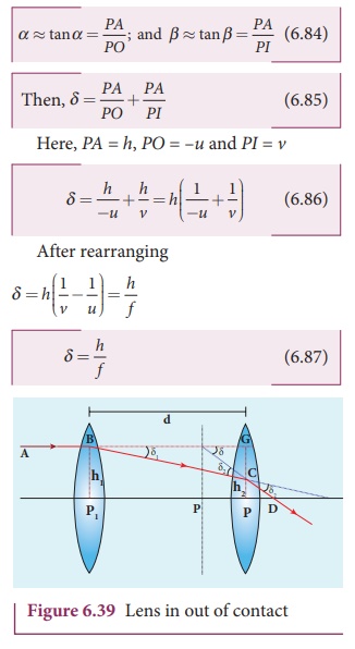
The above equation tells that the angle of deviation is the ratio of height to the focal length. Now, the case of two lenses of focal length f1 and f2 arranged coaxially but separated by a distance d can be considered as shown in Figure 6.39.
For a parallel ray that falls on the arrangement, the two lenses produce deviations δ1 and δ2 respectively and The net deviation δ is.
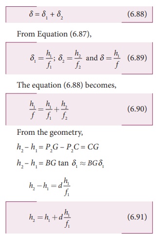
Substituting the above equation in Equation (6.90)
The above equation could be used to find the equivalent focal length. To find the position of the equivalent lens, we can further write from the geometry,
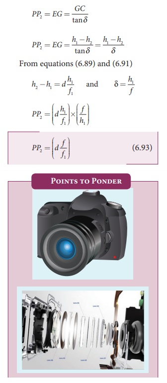
System of combination of lenses is commonly used in designing lenses for cameras, microscopes, telescopes and other optical instruments. They produce better magnification as well as sharpness of the images.
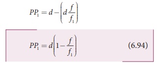
The above equation (6.93) is the position of the equivalent single lens from the second lens. Its position from the first lens is,
The Equation (6.92), (6.93) and (6.94) hold good only for the special case of parallel incident rays or object at infinity. We cannot use these equations if the object is at a finite distance. For finite distance of the object, the image positions must be calculated separately using the lens equation for the two lenses.
EXAMPLE 6.18
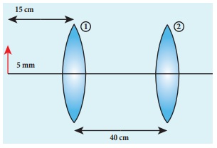
An object of 5 mm height is placed at a distance of 15 cm from a convex lens of focal length 10 cm. A second lens of focal length 5 cm is placed 40 cm from the first lens and 55 cm from the object. Find (a) the position of the final image, (b) its nature and (c) its size.
Solution
Given, h1= 5 mm = 0.5 cm, u1 = –15 cm,
f1 = 10 cm, f2 = 5 cm, d = 40 cm
For the first lens, the lens equation is,
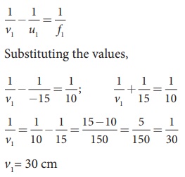
First lens forms image 30 cm to the right of first lens.
Let us find the height of this image.
Equation for magnification is, m = h2/ h1 = v/u
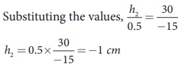
As the height of the lens is negative, the image is inverted, real image.
Object is at 10 cm to the left of the second lens (40–30=10 cm). Hence, u2 = –10 cm
For the second, the lens equation is,
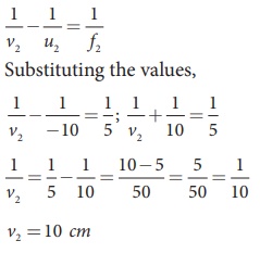
The image is formed 10 cm to the right of the second lens.
Let us find the height of the final image. Assume, the final height of the image formed by the second lens is h2’ and the height of the object for the second lens h1’ is the image height of the first lens, h1′ = h2′

As the height of the image is positive, the image is erect, and it is real.
Silvered lenses
If one of the surfaces of a lens is
silvered from outside, then such a lens is said to be a silvered lens. A
silvered lens is a combination of a lens and a mirror. Light can enter through
the transparent front surface of the lens and get reflected by the sliver
coated rear surface. Hence, light travels two times through the lens as shown
in Figure 6.38.
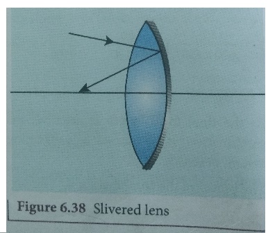
Figure 6.38 Slivered lens
The power P of the silvered lens is,
P= Pl+Pm+Pl
P = 2Pl + Pm
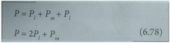
Here, Pl is the power of the lens and Pm is the power of the
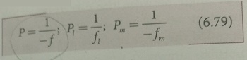
mirror. We know that the power of a lens is the reciprocal of its focal length.
But, the power of a mirror is negative of the reciprocal of its focal length.
This is because, a concave mirror which has negative focal length is a
converging mirror with positive power. Also, a silvered lens is basically a
modified mirror. Thus,
Now equation (6.78) becomes,
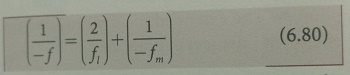
Proper sign conventions are to be
followed for equation (6.80).
Suppose the object distance u and
image distance v are to be found, we
can very well use the mirror equation (6.8), since the silvered lens is a
modified mirror.
1/v + 1/u = 1/f
EXAMPLE 6.18
A thin bicnvex lens is made up of a
glass of refractive index 1.5. The two surfaces have equal radii of curvature
of 30 cm each. One of its surfaces is made reflecting by silvering it from
outside. (a) What is the focal length and power of this silvered lens? (b)
Where should an object be placed in front of this lens so that the image is
formed on the object itself?
Solution
Given, n = 1.5; R₁ = 30 cm; R2 = -30 cm;
(a) Let us find f1 and f2
separately.
Using lens maker's formula we can
find f1.
f1= 30 cm = 0.3 m
Focal length of mirror is, fm
= R2 /2
Substituting the values, fm
= −30 /2 = − 15cm
fm = 15 cm = − 0.15 m
Now the focal length of the slivered
lens is,
1 /−f = 2/f1 + 1/−fm
= 2/30 + 1/15 = 2/15 = 1/7.5
f = −7.5 cm = −0.075 m
The silvered mirror behaves as a
concave mirror with its focal length on left side.
To find the power of the silvered
lens,
P=2Pl + Pm
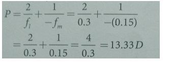
As the power is positive it is a
converging system.
[Note: Here, we come across a
silvered lens which has negative focal length and positive power. Which implies
that the focal length is to the left and the system is a converging one. Such
situations are possible in silvered lenses because a silvered lens is basically
a modified mirror.]
(b) Writing the mirror formula,
1/f = 1/v + 1/u
Here, both u and v are same (v = u)
as the image coincides with the object.
1 / − 7.5 cm = 1/u +1/u
= 2/u
u = −2 × 7.5 cm
u = −15 cm = −0.15 m
The object is to be placed 15 cm to
the left of the silvered lens.
Related Topics