Chapter: Electronic Devices : Power Devices and Display Devices
DIAC (Diode A.C. Swiitch)
DIAC
(DIODE A.C. SWIITCH)
The DIAC
is a full-wa ve or bi-directional semiconductor switch t hat can be turned on
in both forward and reverse pola rities. The DIAC gains its name from the
contraction of the words DIode Alternating Current.
The DIAC
is widely us ed to assist even triggering of a TRIAC wheen used in AC switches.
DIACs are mainly used in dimmer applications and also in starter circuits for
florescent lamps.
A Diac is
two terminal , three layer bi directional device which ca n be switched from
its off state for either polarity of applied voltage.
Circuit symbol
The DIAC
circuit symbol is generated from the two triangles held between two lines as
shown below. In some way this demonstrates the structure of the device which
can be considered also as two junctions
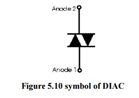
Figure 5.10 symbol of DIAC
The two
terminals of the device are normally designated either Anode 1 and Anode 2 or
Main Terminals 1 and 2, i.e. MT1 and MT2.
Construction
The DIAC can be constructed in either npn or pnp
form. The two leads are connected to p regions of silicon separated by an n-
region. The structure of DIAC is similar to that of a transistor differences
are
·
There is no terminal attached to the base layer
·
The three regions are nearly identical in size. The
doping concentrations are identical to give the device symmetrical properties.
The DIAC
can e fabricated as either a two layer or a five layer structure. In the three
layer structure the switching occurs when the junction that is reverse biased
experiences reverse breakdown. The three layer version of the device is the
more common and can have a break-over voltage of around 30 V. Operation is
almost symmetrical owing to the symmetry of the device.
A five
layer DIAC structure is also available. This does not act in quite the same
manner, although it produces an I-V curve that is very similar to the three
layer version. It can be considered as two break-over diodes connected back to
back.
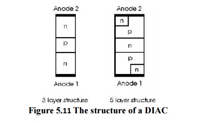
Figure 5.11 The
structure of a DIAC
For most
applications a three layer version of the DIAC is used. It provides sufficient
improvement in switching characteristics. For some applications the five layer
device may be used.
Operation
When a positive or negative voltage is applied
across the terminals of Diac only a small leakage current Ibo will flow through
the device as the applied voltage is increased , the leakage current will
continue to flow until the voltage reaches breakover voltage Vbo at this point
avalanche breakdown of the reverse biased junction occurs and the device
exhibits negative resistance i.e current through the device increases with the
decreasing values of applied voltage the voltage across the device then drops
to break back voltage Vw.
V- I characteristics of a DIAC
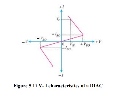
Figure 5.11 V- I
characteristics of a DIAC
For applied positive voltage less than + Vbo and
Negative voltage less than -Vbo , a small leakage current flows thrugh the
device. Under such conditions the diac blocks flow of current and behaves as an
open circuit. the voltage +Vbo and -Vbo are the breakdown voltages and usually
have range of 30 to 50 volts.
When the positive or negative applied voltage is
equal to or greater than tha breakdown voltage Diac begins to conduct and
voltage drop across it beco mes a few volts conduction then continues until the
device current drops below its holding current breakover voltage and holding
current values are identical for the forward and reverse regions of operation.
Applications
Diacs are
used for triggering of triacs in adjustable phase control of a c mains power.
Applications are light dimming heat control universal motor speed control.
Typically the DIAC is placed in series with the gate of a TRIAC. DIACs are
often used in conjunction with TRIACs because these devices do not fire symmetrically
as a result of slight differences between the two halves of the device. This
results in harmonics being generated, and the less symmetrical the device
fires, the greater the level of harmonics produced. It is generally undesirable
to have high levels of harmonics in a power system.
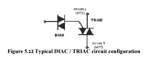
Figure 5.12 Typical
DIAC / TRIAC circuit configuration
To help
in overcoming this problem, a DIAC is often placed in series with the gate.
This device helps make the switching more even for both halves of the cycle.
This results from the fact that its switching characteristic is far more even
than that of the TRIAC. Since the DIAC prevents any gate current flowing until
the trigger voltage has reached a certain voltage in either direction, this
makes the firing point of the TRIAC more even in both directions.
Related Topics