Chapter: Basic Electrical and electronics : Electrical Mechanics
Construction of DC Machines
DC GENERATOR - INTRODUCTION
An
electrical generator is a device that converts
mechanical energy to electrical energy,
generally using electromagnetic induction. The source of mechanical energy may
be a reciprocating or turbine steam
engine, water falling through a turbine or waterwheel, an internal combustion
engine, a wind turbine, a hand crank, or any other source of mechanical energy.
The
Dynamo was the first electrical generator capable of delivering power for industry.
The dynamo uses electromagnetic principles to convert mechanical rotation into
an alternating electric current. A dynamo machine consists of a stationary
structure which generates a strong magnetic field, and a set of rotating
windings which turn within that field. On small machines the magnetic field may
be provided by a permanent magnet; larger machines have the magnetic field
created by electromagnets. The energy conversion in generator is based on the
principle of the production of dynamically induced e.m.f. whenever a conductor
cuts magneticic flux, dynamically induced e.m.f is produced in it according to
Faraday's Laws of Electromagnetic induction. This e.m.f causes a current to
flow if the conductor circuit is closed.
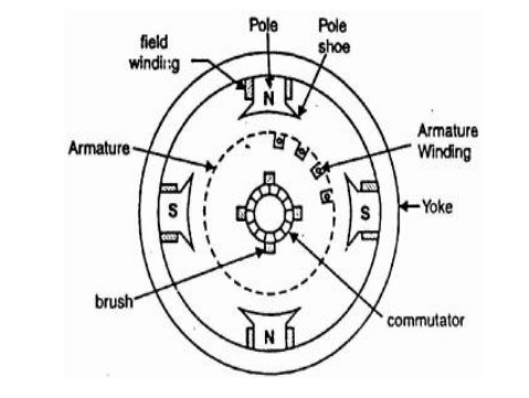
CONSTRUCTION OF D.C. MACHINES
A D.C.
machine consists mainly of two part the stationary part called stator and the
rotating part called rotor.The stator consists of main poles used to produce
magnetic flux ,commutating poles or interpoles in between the main poles to
avoid sparking at the commutator but in the case of small machines sometimes
the interpoles are avoided and finally the frame or yoke which forms the
supporting structure of the machine. The rotor consist of an armature a
cylindrical metallic body or core with slots in it to place armature windings
or bars,a commutator and brush gears The magnetic flux path in a motor or
generator is show below and it is called the magnetic structure of generator or
motor.
The major parts can be identified as,
1. Frame
2. Poles
3. Armature
4. Field
winding
5. Commutator
6. Brush
7. Other
mechanical parts
Frame
Frame is
the stationary part of a machine on which the main poles and commutator poles
are bolted and it forms the supporting structure by connecting the frame to the
bed plate. The ring shaped body portion of the frame which makes the magnetic
path for the magnetic fluxes from the main poles and interpoles is called Yoke.
Why we use cast steel instead of cast iron for the
construction of Yoke?
In early
days Yoke was made up of cast iron but now it is replaced by cast steel.This is
because cast iron is saturated by a flux density of 0.8 Wb/sq.m where as
saturation with cast iron steel is about 1.5 Wb/sq.m.So for the same magnetic
flux density the cross section area needed for cast steel is less than cast
iron hence the weight of the machine too.If we use cast iron there may be
chances of blow holes in it while casting.so now rolled steels are developed
and these have consistent magnetic and mechanical properties.
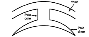
poles:
Solid
poles of fabricated steel with separate/integral pole shoes are fastened to the
frame by means of bolts. Pole shoes are generally laminated. Sometimes pole
body and pole shoe are formed from the same laminations. The pole shoes are
shaped so as to have a slightly increased air gap at the tips. Inter-poles are
small additional poles located in between the main poles.
These can
be solid, or laminated just as the main poles. These are also fastened to the
yoke by bolts. Sometimes the yoke may be slotted to receive these poles. The
inter poles could be of tapered section or of uniform cross section. These are
also called as commutating poles or com poles. The width of the tip of the com
pole can be about a rotor slot pitch.
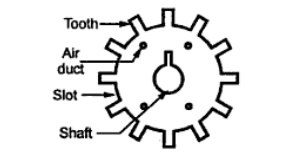
Armature
The
armature is where the moving conductors are located. The armature is
constructed by stacking laminated sheets of silicon steel. Thickness of these
lamination is kept low to reduce eddy current losses. As the laminations carry
alternating flux the choice of suitable material, insulation coating on the
laminations, stacking it etc are to be done more carefully. The core is divided
into packets to facilitate ventilation. The winding cannot be placed on the
surface of the rotor due to the mechanical forces coming on the same. Open
parallel sided equally spaced slots are normally punched in the rotor
laminations.
These
slots house the armature winding. Large sized machines employ a spider on which
the laminations are stacked in segments. End plates are suitably shaped so as
to serve as ’Winding supporters’. Armature construction process must ensure
provision of sufficient axial and radial ducts to facilitate easy removal of
heat from the armature winding.
Field windings:
In the
case of wound field machines (as against permanent magnet excited machines) the
field winding takes the form of a concentric coil wound around the main poles.
These carry the excitation current and produce the main field in the machine.
Thus the poles are created electromagnetically. Two types of windings are
generally employed. In shunt winding large number of turns of small section
copper conductor is used. The resistance of such winding would be an order of
magnitude larger than the armature winding resistance. In the case of series
winding a few turns of heavy cross section conductor is used. The resistance of
such windings is low and is comparable to armature resistance. Some machines
may have both the windings on the poles. The total ampere turns required to
establish the necessary flux under the poles is calculated from the magnetic
circuit calculations. The total mmf required is divided equally between north
and south poles as the poles are produced in pairs. The mmf required to be
shared between shunt and series windings are apportioned as per the design
requirements. As these work on the same magnetic system they are in the form of
concentric coils. Mmf ’per pole’ is normally used in these calculations.
Armature winding As mentioned earlier, if the armature coils are wound on the
surface of the armature, such construction becomes mechanically weak. The
conductors may fly away when the armature starts rotating. Hence the armature
windings are in general pre-formed, taped and lowered into the open slots on
the armature. In the case of small machines, they can be hand wound. The coils
are prevented from flying out due to the centrifugal forces by means of bands
of steel wire on the surface of the rotor in small groves cut into it. In the
case of large machines slot wedges are additionally used to restrain the coils
from flying away. The end portion of the windings are taped at the free end and
bound to the winding carrier ring of the armature at the commutator end. The
armature must be dynamically balanced to reduce the centrifugal forces at the
operating speeds. Compensating winding One may find a bar winding housed in the
slots on the pole shoes. This is mostly found in d.c. machines of very large
rating. Such winding is called compensating winding. In smaller machines, they
may be absent.
Commutator:
Commutator
is the key element which made the d.c. machine of the present day possible. It
consists of copper segments tightly fastened together with mica/micanite
insulating separators
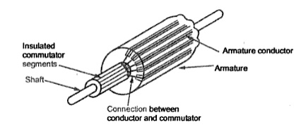
on an
insulated base. The whole commutator forms a rigid and solid assembly of
insulated copper strips and can rotate at high speeds. Each commutator segment
is provided with a ’riser’ where the ends of the armature coils get connected.
The surface of the commutator is machined and surface is made concentric with
the shaft and the current collecting brushes rest on the same. Under-cutting
the mica insulators that are between these commutator segments has to be done
periodically to avoid fouling of the surface of the commutator by mica when the
commutator gets worn out. Some details of the construction of the commutator
are seen in Fig
Brush and brush holders:
Brushes
rest on the surface of the commutator. Normally electro-graphite is used as
brush material. The actual composition of the brush depends on the peripheral
speed of the commutator and the working voltage. The hardness of the graphite
brush is selected to be lower than that of the commutator. When the brush wears
out the graphite works as a solid lubricant reducing frictional coefficient.
More number of relatively smaller width brushes are preferred in place of large
broad brushes. The brush holders provide slots for the brushes to be placed. The
connection Brush holder with a Brush and Positioning of the brush on the
commutator from the brush is taken out by means of flexible pigtail. The
brushes are kept pressed on the commutator with the help of springs. This is to
ensure proper contact between the brushes and the commutator even under high
speeds of operation. Jumping of brushes must be avoided to ensure arc free
current collection and to keep the brushcontact drop low. Other mechanical
parts End covers, fan and shaft bearings form other important mechanical parts.
End covers are completely solid or have opening for ventilation. They support
the bearings which are on the shaft. Proper machining is to be ensured for easy
assembly. Fans can be external or internal. In most machines the fan is on the
non-commutator end sucking the air from the commutator end and throwing the
same out. Adequate quantity of hot air removal has to be ensured. Bearings
Small machines employ ball bearings at both ends. For larger machines roller
bearings are used especially at the driving end. The bearings are mounted
press-fit on the shaft. They are housed inside the end shield in such a manner
that it is not necessary to remove the bearings from the shaft for dismantling.
End Shields or Bearings
If the
armature diameter does not exceed 35 to 45 cm then in addition to poles end
shields or frame head with bearing are attached to the frame.If the armature
diameter is greater than 1m pedestral
type bearings are mounted on the machine bed plate outside the frame.These
bearings could be ball or roller
type but generally plain pedestral bearings are employed.If the diameter of the
armature is large a brush holder yoke
is generally fixed to the frame.
Related Topics