Chapter: Basic Electrical and electronics : Electrical Mechanics
Construction, Principle of Operation of Single Phase Transformer
TRANSFORMER
INTRODUCTION
A
TRANSFORMER is a device that transfers electrical energy from one circuit to
another by electromagnetic induction (transformer action). The electrical
energy is always transferred without a change in frequency, but may involve
changes in magnitudes of voltage and current. Because a transformer works on
the principle of electromagnetic induction, it must be used with an input
source voltage that varies in amplitude. There are many types of power that fit
this description; for ease of explanation and understanding, transformer action
will be explained using an ac voltage as the input source.
BASIC OPERATION OF A TRANSFORMER
In its
most basic form a transformer consists of: A primary coil or winding.
A
secondary coil or winding.
A core
that supports the coils or windings.
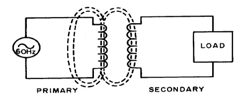
Refer to
the transformer circuit in figure as you read the following explanation: The
primary winding is connected to a 60 hertz ac voltage source. The magnetic
field (flux) builds up (expands) and collapses (contracts) about the primary
winding. The expanding and contracting magnetic field around the primary
winding cuts the secondary winding and induces an alternating voltage into the
winding. This voltage causes alternating current to flow through the load. The
voltage may be stepped up or down depending on the design of the primary and
secondary windings.
AN IDEAL TRANSFORMER
An ideal
transformer is shown in the adjacent figure. Current passing through the
primary coil creates a magnetic field. The primary and secondary coils are
wrapped around a core of very high magnetic permeability, such as iron, so that
most of the magnetic flux passes through both the primary and secondary coils.
BASIC WORKING PRINCIPLE OF TRANSFORMER
A transformer can be defined as a static device which helps in
the transformation of electric power in one circuit to electric power of the
same frequency in another circuit. The voltage can be raised or lowered in a
circuit, but with a proportional increase or decrease in the current ratings.
The main principle of operation of a transformer is mutual
inductance between two circuits which is linked by a common magnetic flux. A
basic transformer consists of two coils that are electrically separate and
inductive, but are magnetically linked through a path of reluctance. The
working principle of the transformer can be understood from the figure below.

As shown above the transformer has primary and secondary
windings. The core laminations are joined in the form of strips in between the
strips you can see that there are some narrow gaps right through the
cross-section of the core. These staggered joints are said to be
‘imbricated’. Both the coils have high mutual inductance. A
mutual electro-motive force is induced in the transformer from the alternating
flux that is set up in the laminated core, due to the coil that is connected to
a source of alternating voltage. Most of the alternating flux developed by this
coil is linked with the other coil and thus produces the mutual induced
electro-motive force. The so produced electro-motive force can be explained
with the help of Faraday’s laws of Electromagnetic Induction as
e=M*dI/dt
If the second coil circuit is closed, a current flows in it and
thus electrical energy is transferred magnetically from the first to the second
coil.
The alternating current supply is given to the first coil and
hence it can be called as the primary winding. The energy is drawn out from the
second coil and thus can be called as the secondary winding.
In short, a transformer carries the operations shown below:
Transfer of electric power from one circuit to another.
Transfer of electric power without any change in frequency.
Transfer with the principle of electromagnetic induction.
The two electrical circuits are linked by mutual induction
TRANSFORMER CONSTRUCTION
Two coils of wire (called windings) are wound on some type of core
material. In some cases the coils of wire are wound on a cylindrical or
rectangular cardboard form. In effect, the core material is air and the
transformer is called an AIR-CORE TRANSFORMER. Transformers used at low
frequencies, such as 60 hertz and 400 hertz, require a core of low-reluctance
magnetic material, usually iron. This type of transformer is called an
IRON-CORE TRANSFORMER. Most power transformers are of the iron-core type.
The
principle parts of a transformer and their functions are:
The CORE, which provides a path for the magnetic lines of flux.
The PRIMARY WINDING, which receives energy from the ac source.
The SECONDARY WINDING, which receives energy from the primary winding
and delivers it to the load.
The ENCLOSURE, which protects the above components from dirt, moisture,
and mechanical damage.
(i) CORE
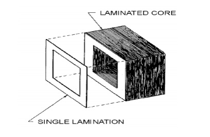
There are two main shapes of cores used in laminated-steel-core
transformers. One is the HOLLOWCORE, so named because the core is shaped with a
hollow square through the center. This shape of core. Notice that the core is
made up of many laminations of steel it shows how the transformer windings are
wrapped around both sides of the core.
(ii)
WINDINGS
As stated above, the transformer consists of two coils called WINDINGS
which are wrapped around a core. The transformer operates when a source of ac
voltage is connected to one of the windings and a load device is connected to
the other. The winding that is connected to the source is called the PRIMARY
WINDING. The winding that is connected to the load is called the SECONDARY
WINDING. The primary is wound in layers directly on a rectangular cardboard
form.
Related Topics