Chapter: Basic Electrical and electronics : Electrical Mechanics
DC Generator Characteristics
DC GENERATOR CHARACTERISTICS:
The three
most important characteristics or curves of a d.c generator are
1. OpenCircuitCharacteristic (O.C.C.)
This
curve shows the relation between the generated e.m.f. at no-load (E0) and the
field current (If) at constant speed. It is also known as magnetic
characteristic or no-load saturation curve. Its shape is practically the same
for all generators whether separately or self-excited. The data for O.C.C.
curve are obtained experimentally by operating the generator at no load and
constant speed and recording the change in terminal voltage as the field
current is varied.
2. Internal or Total characteristic (E/Ia)
This
curve shows the relation between the generated e.m.f. on load (E) and the
armature current (Ia). The e.m.f. E is less than E0 due to the demagnetizing
effect of armature reaction. Therefore, this curve will lie below the open
circuit characteristic (O.C.C.). The internal characteristic is of interest
chiefly to the designer. It cannot be obtained directly by experiment. It is
because a voltmeter cannot read the e.m.f. generated on load due to the voltage
drop in armature resistance. The internal characteristic can be obtained from
external characteristic if winding resistances are known because armature
reaction effect is included in both characteristics
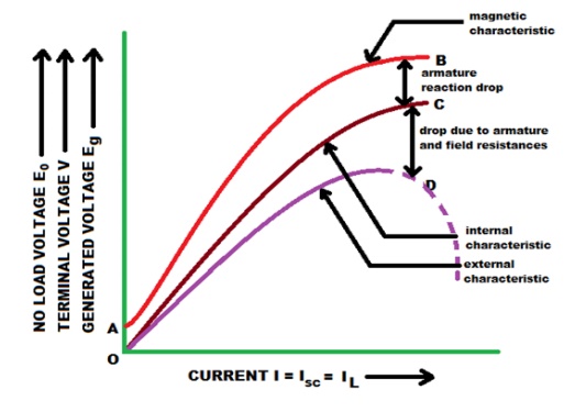
3. External characteristic (V/IL)
This
curve shows the relation between the terminal voltage (V) and load current
(IL). The terminal voltage V will be less than E due to voltage drop in the
armature circuit. Therefore, this curve will lie below the internal
characteristic. This characteristic is very important in determining the
suitability of a generator for a given purpose. It can be obtained by making
simultaneous
1 characteristics Series of DC generator:
Fig.
shows the connections of a series wound generator. Since there is only one
current (that which flows through the whole machine), the load currentis the
same as the exciting current.
(i)O.C.C.
Curve 1
shows the open circuit characteristic (O.C.C.) of a series generator. It can be
obtainedexperimentally by disconnecting the field winding from the machine and
exciting it from aseparate d.c. source
(ii) Internal characteristic
Curve 2
shows the total or internal characteristic of a series generator. It gives the
relation between the generated e.m.f. E. on load and armature current. Due to
armature reaction, the flux in the machine will be less than the flux at no
load. Hence, e.m.f. E generated under load conditions will be less than the
e.m.f. EO generated under no load conditions. Consequently, internal
characteristic curve generated under no load conditions. Consequently, internal
characteristic curve lies below the O.C.C. curve; the difference between them
representing the effect of armature reaction
(iii)Externalcharacteristic
Curve 3
shows the external characteristic of a series generator. It gives the relation
between terminal voltage and load current IL.
V= E-Ia(Ra+Rse)
Therefore,
external characteristic curve will lie below internal characteristic curve by
an amount equal to ohmic drop[i.e., Ia(Ra+Rse)] in the machine. The internal
and external characteristics of a d.c. series generator can be plotted from one
another as shown in Fig. Suppose we are given the internal characteristic of
the generator. Let the line OC represent the resistance of the whole machine
i.e. Ra+Rse.If the load current is OB, drop in the machine is AB i.e.
AB = Ohmic drop in the machine = OB(Ra+Rse)
Now raise
a perpendicular from point B and mark a point b on this line such that ab = AB.
Then point b will lie on the external characteristic of the generator.
Following similar procedure, other points of external characteristic can be
located. It is easy to see that we can also plot internal characteristic from
the external characteristic.
Characteristics Shunt DC generator:
Fig shows
the connections of a shunt wound generator. The armature current Ia splits up
into two parts; a small fraction Ish flowing through shunt field winding while
the major part IL goes to the external load.
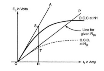
(i) O.C.C.
The
O.C.C. of a shunt generator is similar in shape to that of a series generator
as shown in Fig. The line OA represents the shunt field circuit resistance.
When the generator is run at normal speed, it will build up a voltage OM. At
no-load, the terminal voltage of the generator will be constant (= OM)
represented by the horizontal dotted line MC.
(ii)Internal characteristic
When the
generator is loaded, flux per pole is reduced due to armature reaction.
Therefore, e.m.f. E generated on load is less than the e.m.f. generated at no
load.As a result, the internal characteristic (E/Ia) drops down slightly as
shown in Fig.
(iii)External characteristic
Curve 2
shows the external characteristic of a shunt generator. It gives the relation
between terminal voltage V and load current IL.
V = E –
IaRa = E -(IL +Ish)Ra
Therefore,
external characteristic curve will lie below the internal characteristic curve
by an amount equal to drop in the armature circuit [i.e., (IL +Ish)Ra ] as
shown in Fig
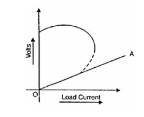
Critical External Resistance for Shunt Generator
If the
load resistance across the terminals of a shunt generator is decreased, then
load current increase? However, there is a limit to the increase in load
current with the decrease of load resistance. Any decrease of load resistance
beyond this point, instead of increasing the current, ultimately results in
reduced current. Consequently, the external characteristic turns back
(dottedcurve) as shown in Fig. The tangent OA to the curve represents the
minimum external resistance required to excite the shunt generator on load and
is called critical external resistance. If the resistance of the external
circuit is less than the critical external resistance (represented by tangent
OA in Fig, the machine will refuse to excite or will de-excite if already
running This means that external resistance is so low as virtually to short
circuit the machine and so doing away with its excitation.
There are
two critical resistances for a shunt generator viz.,
(i)
critical field resistance
(ii)
critical external resistance. For the shunt
generator to build up voltage, the former should not be exceeded and the latter
must not be gone below
Characteristics compound generator:
In a
compound generator, both series and shunt excitation are combined as shown in
Fig. The shunt winding can be connected either across the armature only
(short-shunt connection S) or across armature plus series field (long-shunt
connection G). The compound generator can be cumulatively compounded or
differentially compounded generator. The latter is rarely used in practice.
Therefore, we shall discuss the characteristics of cumulatively compounded
generator. It may be noted that external characteristics of long and short
shunt compound generators are almost identical.
External characteristic
Fig.
shows the external characteristics of a cumulatively compounded generator. The
series excitation aids the shunt excitation. The degree of compounding depends
upon the increase in series excitation with the increase in load current.
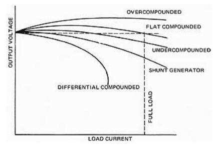
(i) If series
winding turns are so adjusted that with the increase in load current the
terminal voltage increases, it is called over-compounded generator. In such a
case, as the load current increases, the series field m.m.f. increases and
tends to increase the flux and hence the generated voltage. The increase in
generated voltage is greater than the IaRa drop so that instead of decreasing,
the terminal voltage increases as shown by curve A in Fig.
(ii) If series
winding turns are so adjusted that with the increase in load current, the
terminal voltage substantially remains constant, it is called flat-compounded
generator. The series winding of such a machine has lesser number of turns than
the one in over-compounded machine and, therefore, does not increase the flux
as much for a given load current. Consequently, the full-load voltage is nearly
equal to the no-load voltage as indicated by curve B in Fig
(iii) If series
field winding has lesser number of turns than for a flat compounded machine,
the terminal voltage falls with increase in load current as indicated by curve
C m Fig. Such a machine is called under-compounded generator.
Related Topics