Chapter: Basic Electrical and electronics : Electrical Mechanics
Types of Single phase induction Motor
STARTING METHODS
The single-phase IM has no starting torque, but has resultant torque, when it rotates at any other speed, except synchronous speed. It is also known that, in a balanced two-phase IM having two windings, each having equal number of turns and placed at a space angle of 900(electrical), and are fed from a balanced two-phase supply, with two voltages equal in magnitude, at an angle of 900, the rotating magnetic fields are produced, as in a three-phase IM. The torque-speed characteristic is same as that of a three-phase one, having both starting and also running torque as shown earlier. So, in a single-phase IM, if an auxiliary winding is introduced in the stator, in addition to the main winding, but placed at a space angle of 900 (electrical), starting torque is produced. The currents in the two (main and auxiliary) stator windings also must be at an angle of 900 , to produce maximum starting torque, as shown in a balanced two-phase stator. Thus, rotating magnetic field is produced in such motor, giving rise to starting torque. The various starting methods used in a single-phase IM are described here.
1. RESISTANCE SPLIT-PHASE MOTOR
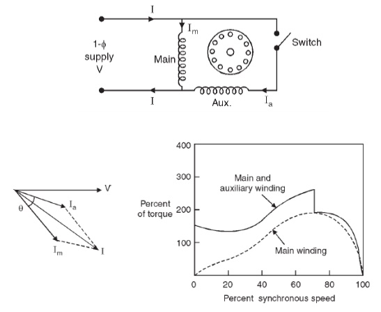
The schematic (circuit) diagram of this motor is given in Fig. As detailed earlier, another (auxiliary) winding with a high resistance in series is to be added along with the main winding in the stator. This winding has higher resistance to reactance () ratio as compared to that in the main winding, and is placed at a space angle of from the main winding as given earlier. The phasor diagram of the currents in two windings and the input voltage is shown in Fig.The current () in the auxiliary winding lags the voltage (V) by an angle, aaXR/°90aIaφ, which is small, whereas the current () in the main winding lags the voltage (V) by an angle, mImφ, which is nearly . The phase angle between the two currents is (°90aφ−°90), which should be at least . This results in a small amount of starting torque. The switch, S (centrifugal switch) is in series with the auxiliary winding. It automatically cuts out the auxiliary or starting winding, when the motor attains a speed close to full load speed. The motor has a starting torque of 100−200% of full load torque, with the starting current as 5-7 times the full load current. The torque-speed characteristics of the motor with/without auxiliary winding are shown in Fig.The change over occurs, when the auxiliary winding is switched off as given earlier. The direction of rotation is reversed by reversing the terminals of any one of two windings, but not both, before connecting the motor to the supply terminals. This motor is used in applications, such as fan, saw, small lathe, centrifugal pump, blower, office equipment, washing machine, etc.
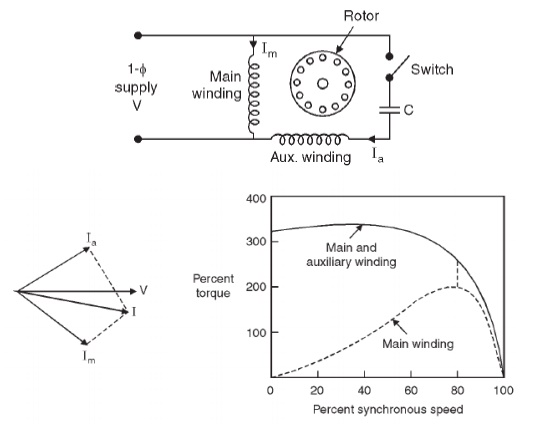
2. CAPACITOR-START MOTOR
The schematic (circuit) diagram of this motor is given in Fig. It may be observed that a capacitor along with a centrifugal switch is connected in series with the auxiliary winding, which is being used here as a starting winding. The capacitor may be rated only for intermittent duty, the cost of which decreases, as it is used only at the time of starting. The function of the centrifugal switch has been described earlier. The phasor diagram of two currents as described earlier, and the torque-speed characteristics of the motor with/without auxiliary winding, are shown in Fig. This motor is used in applications, such as compressor, conveyor, machine tool drive, refrigeration and air-conditioning equipment, etc.
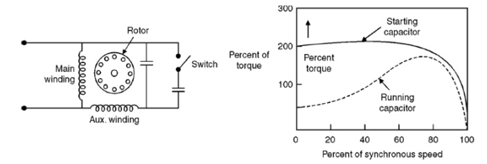
3. Capacitor-start and Capacitor-run Motor
In this motor two capacitors − Csfor starting, and Cr for running, are used. The first capacitor is rated for intermittent duty, as described earlier, being used only for starting. A centrifugal switch is also needed here. The second one is to be rated for continuous duty, as it is used for running. The phasor diagram of two currents in both cases, and the torque-speed characteristics with two windings having different values of capacitors, are shown in respectively. The phase difference between the two currents is (φm+φa>900) in the first case (starting), while it is900 for second case (running). In the second case, the motor is a balanced two phase one, the two windings having same number of turns and other conditions as given earlier, are also satisfied. So, only the forward rotating field is present, and the no backward rotating field exists. The efficiency of the motor under this condition is higher. Hence, using two capacitors, the performance of the motor improves both at the time of starting and then running. This motor is used in applications, such as compressor, refrigerator, etc.
Beside the above two types of motors, a Permanent Capacitor Motor with the same capacitor being utilised for both starting and running, is also used. The power factor of this motor, when it is operating (running), is high. The operation is also quiet and smooth. This motor is used in applications, such as ceiling fans, air circulator, blower, etc.
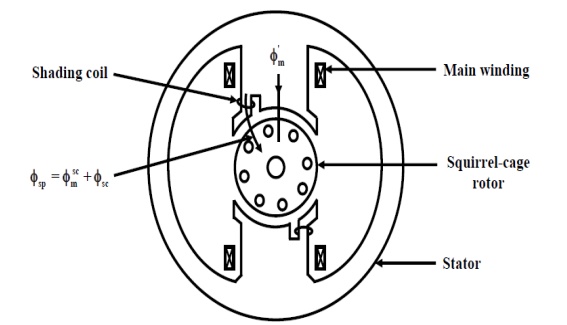
4. Shaded-pole Motor
A typical shaded-pole motor with a cage rotor is shown in Fig. 34.8a. This is a single-phase induction motor, with main winding in the stator. A small portion of each pole is covered with a short-circuited, single-turn copper coil called the shading coil. The sinusoidally varying flux created by ac (single-phase) excitation of the main winding induces emf in the shading coil. As a result, induced currents flow in the shading coil producing their own flux in the shaded portion of the pole.
Let the main winding flux be φm=φmaxsinwt
The reversal of the direction of rotation, where desired, can be achieved by providing two shading coils, one on each end of every pole, and by open-circuiting one set of shading coils and by short-circuiting the other set.
The fact that the shaded-pole motor is single-winding (no auxiliary winding) self-starting one, makes it less costly and results in rugged construction. The motor has low efficiency and is usually available in a range of 1/300 to 1/20 kW. It is used for domestic fans, record players and tape recorders, humidifiers, slide projectors, small business machines, etc. The shaded-pole principle is used in starting electric clocks and other single-phase synchronous timing motors.
no starting torque is produced in the single-phase induction motor with only one (main) stator winding, as the flux produced is a pulsating one, with the winding being fed from single phase supply. Using double revolving field theory, the torque-speed characteristics of this type of motor are described, and it is also shown that, if the motor is initially given some torque in either direction, the motor accelerates in that direction, and also the torque is produced in that direction. Then, the various types of single phase induction motors, along with the starting methods used in each one are presented. Two stator windings − main and auxiliary, are needed to produce the starting torque. The merits and demerits of each type, along with their application area, are presented. The process of production of starting torque in shade-pole motor is also described in brief. In the next module consisting of seven lessons, the construction and also operation of dc machines, both as generator and motor, will be discussed.
Related Topics