Chapter: Basic Electrical and electronics : Electrical Mechanics
Basic Equations and Applications of Single Phase Transformer
EMF Equation of Transformer:
Let the applied voltage V1 applied to the primary of a transformer, with
secondary open-circuited, be sinusoidal (or sine wave). Then the current I1,
due to applied voltage V1, will also be a sine wave. The mmf N1 I1 and core
flux Ø will follow the variations of I1 closely. That is the flux is in time
phase with the current I1 and varies sinusoidally.
Let,
NA = Number of turns in primary
NB = Number of turns in secondary
Ømax = Maximum flux in the core in webers = Bmax
X A f = Frequency of alternating current input in hertz (HZ)
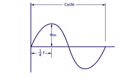
As shown in figure above, the core flux increases from its zero
value to maximum value Ømax in one quarter of the cycle , that is in
¼ frequency second.
Therefore, average rate of change of flux = Ømax/ ¼ f
= 4f ØmaxWb/s
Now, rate of change of flux per turn means induced electro
motive force in volts. Therefore,
average electro-motive force induced/turn = 4f Ømaxvolt
If flux Ø varies sinusoidally, then r.m.s value of induced e.m.f
is obtained by multiplying the average value with form factor.
Form Factor = r.m.s. value/average value = 1.11 Therefore,
r.m.s value of e.m.f/turn = 1.11 X 4f Ømax = 4.44f Ømax
Now, r.m.s value of induced e.m.f in the whole of primary winding
= (induced e.m.f./turn) X Number of primary turns
Therefore,
EA = 4.44f NAØmax = 4.44fNABmA
Similarly, r.m.s value of
induced e.m.f in secondary is
EB = 4.44f NB Ømax = 4.44fNBBmA
In an ideal transformer on no
load, VA = EA and VB = EB , where VB is the terminal voltage
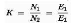
Voltage Transformation Ratio.
The ratio of secondary voltage to primary voltage is known as the
voltage transformation ratio and is designated by letter K. i.e.
Voltage
transformation ratio, K = V2/V1 = E2/E1 = N2/N1
Current Ratio.
The ratio of secondary current to primary current is known as current
ratio and is reciprocal of voltage transformation ratio in an ideal
transformer.
Transformer on No Load.
When the
primary of a transformer is connected to the source of an ac supply and the
secondary is open circuited, the transformer is said to be on no load. The
Transformer on No Load alternating applied voltage will cause flow of an
alternating current I0 in the primary
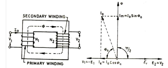
winding,
which will create alternating flux Ø. No-load current I0, also known as
excitation or exciting current, has two components the magnetizing component Im
and the energy component Ie. Im is used to create the flux in the core and Ie
is used to overcome the hysteresis and eddy current losses occurring in the
core in addition to small amount of copper losses occurring in the primary only
(no copper loss occurs in the secondary, because it carries no current, being
open circuited.)
From
vector diagram shown in above it is obvious that
1. Induced
emfs in primary and secondary windings, E1 and E2 lag the main flux Ø by and
are in phase with each other.
2. Applied
voltage to primary V1 and leads the main flux Ø by and is in phase opposition
to E1.
3. Secondary
voltage V2 is in phase and equal to E2 since there is no voltage drop in
secondary.
4. Im is in
phase with Ø and so lags V1 by
5. Ie is in
phase with the applied voltage V1.
6. Input
power on no load = V1Ie = V1I0 cos Ø0 where Ø0 = tan-1
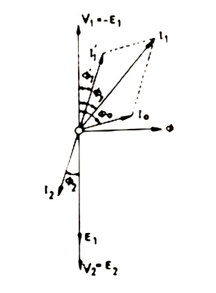
Transformer on Load:
The
transformer is said to be loaded, when its secondary circuit is completed
through an impedance or load. The magnitude and phase of secondary current
(i.e. current flowing through secondary) I2 with respect to secondary terminals
depends upon the characteristic of the load i.e. current I2 will be in phase,
lag behind and lead the terminal voltage V+2+ respectively when the load is
non-inductive, inductive and capacitive. The net flux passing through the core
remains almost constant from no-load to full load irrespective of load
conditions and so core losses remain almost constant from no-load to full load.
Vector diagram for an ideal transformer supplying inductive load is shown
Resistance
and Leakage Reactance In actual practice, both of the primary and secondary
windings have got some ohmic resistance causing voltage drops and copper losses
in the windings. In actual practice, the total flux created does not link both
of the primary and secondary windings but is divided into three components
namely the main or mutual flux Ø linking both of the primary and secondary
windings, primary leakage flux ØL1 linking with primary winding only
and secondary leakage flux ØL2 linking with secondary winding only.
The primary leakage flux ØL1 is produced by primary ampere-turns and
is proportional to primary current, number of primary turns being fixed. The
primary leakage flux ØL1 is in phase with I1 and produces
self induced emf ØL1 is in phase with I1 and produces
self induced emf EL1 given as 2f L1 I1 in the
primary winding.
The self
induced emf divided by the primary current gives the reactance of primary and
is denoted by X1.
i.e. X1 =
EL1/I1 = 2πfL1I1/I1 = 2FL1,
Similarly
leakage reactance of secondary X2 = EL2/E2 = 2fπL2I2/I2 = 2πfL2
Equivalent
Resistance and Reactance. The equivalent resistances and reactance’s of
transformer windings referred to primary and secondary sides are given as below
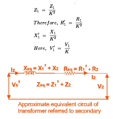
Referred to primary side Equivalent resistance,
Equivalent
resistance, = X'1 = Referred to secondary side Equivalent resistance,
Equivalent
resistance, = X2 + K2X1 Where K is the transformation ratio.
EQUIVALENT CIRCUIT OF TRANSFORMER
Equivalent
impedance of transformer is essential to be calculated because the electrical
power transformer is an electrical power system equipment for estimating
different parameters of electrical power system which may be required to
calculate total internal impedance of an electrical power transformer, viewing
from primary side or secondary side as per requirement. This calculation
requires equivalent circuit of transformer referred to primary or equivalent
circuit of transformer referred to secondary sides respectively. Percentage
impedance is also very essential parameter of transformer. Special attention is
to be given to this parameter during installing a transformer in an existing
electrical power system. Percentage impedance of different power transformers
should be properly matched during parallel operation of power transformers. The
percentage impedance can be derived from equivalent impedance of transformer
so, it can be said that equivalent circuit of transformer is also required
during calculation of % impedance.
Equivalent Circuit of Transformer Referred to
Primary
For drawing equivalent
circuit of transformer referred to primary, first we have to establish
general equivalent circuit of
transformer then, we will modify it for referring from primary side. For
doing this, first we need to recall the complete vector diagram of a
transformer which is shown in the figure below.
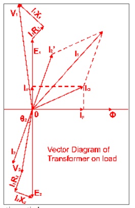
Let us
consider the transformation ratio be,
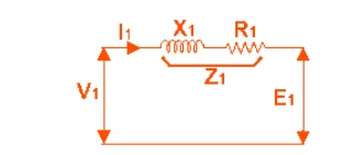
In the
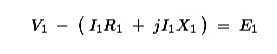
figure right, the applied voltage to the primary is V1 and voltage across the primary winding is E1. Total current supplied to primary is I1. So the voltage V1 applied to the primary is partly
dropped by I1Z1 or I1R1 + j.I1X1
before it appears across primary winding. The voltage appeared across winding is countered by primary
induced emf E1.
The
equivalent circuit for that equation can be drawn as below,
From the
vector diagram above, it is found that the total primary current I1 has two components, one is no - load
component Io and the other is load component I2′. As this
primary current has two a component or branches, so there must be a
parallel path with primary winding of transformer. This parallel path of current is known as excitation branch of equivalent circuit
of transformer. The resistive and reactive branches of the excitation circuit
can be represented as

The load
component I2′ flows through the primary winding of transformer and
induced voltage across the winding is E1
as shown in the figure right. This induced voltage E1transforms to
secondary and it is E2 and load component of primary current I2′ is transformed to secondary as
secondary current I2. Current
of secondary is I 2. So the voltage E2 across secondary winding is partly
dropped by I2Z2 or I2R2 + j.I2X2
before it appears across load. The load voltage is V2.
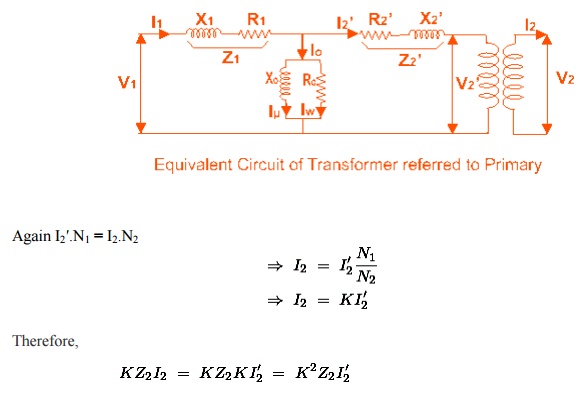
From
above equation, secondary impedance of transformer referred to primary is,
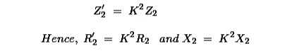
So, the complete equivalent circuit of transformer referred to
primary is shown in the figure below,
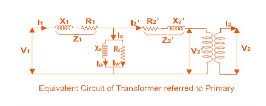
Approximate Equivalent Circuit of Transformer
Since Io
is very small compared to I1, it is less than 5% of full load
primary current, Iochanges the voltage drop insignificantly. Hence, it is good
approximation to ignore the excitation circuit in approximate equivalent
circuit of transformer. The winding resistanceand reactance being in series can
now be combined into equivalent resistance and reactance of transformer,
referred to any particular side. In this case it is side 1 or primary side.
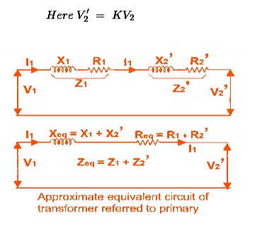
Equivalent Circuit of Transformer Referred to
Secondary
In
similar way, approximate equivalent circuit of transformer referred to
secondary can be drawn. Where equivalent impedance of transformer referred to
secondary, can be derived as
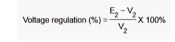
VOLTAGE REGULATION
The
voltage regulation is the percentage of voltage difference between no load and
full load voltages of a transformer with respect to its full load voltage.
Explanation of Voltage Regulation of Transformer
Say an
electrical power transformer is open circuited, means load is not connected
with secondary terminals. In this situation, the secondary terminalvoltage of
the transformer will be its secondary induced emf E2. Whenever full
load is connected to the secondary terminals of the transformer, ratedcurrent I2
flows through the secondary circuit and voltage drop comes into picture. At
this situation, primary winding will also draw equivalent full load current
from source. The voltagedrop in the secondary is I2Z2
where Z2 is the secondary impedance of transformer. Now if at this
loading condition, any one measures the voltage between secondary terminals, he
or she will getvoltage V2 across load terminals which is obviously
less than no load secondary voltage E2 and this is because of I2Z2
voltage drop in the transformer.
Expression
of Voltage Regulation of Transformer, represented in percentage, is
Related Topics