Chapter: Clinical Anesthesiology: Perioperative & Critical Care Medicine: Critical Care
Positive-Pressure Ventilators
Positive-Pressure
Ventilators
Positive-pressure ventilators periodically create a pressure gradient
between the machine circuit and alveoli that results in inspiratory gas flow.
Exhala-tion occurs passively. Ventilators and their control mechanisms can be
powered pneumatically (by a pressurized gas source), electrically, or by both
mechanisms. Gas flow is either derived directly from the pressurized gas source
or produced by the action of a rotary or linear piston. This gas flow then
either goes directly to the patient (single-circuit system) or, as commonly
occurs with oper-ating room ventilators, compresses a reservoir bag or bellows
that is part of the patient circuit (double-circuit system).
All ventilators have four phases: inspiration, the changeover from
inspiration to expiration, expiration, and the changeover from expiration to
inspiration. These phases are defined by VT, ventilatory rate, inspiratory
time, inspiratory gas flow, and expiratory time.
Classification of Ventilators
The complexity of modern ventilators defies
simple classification. Incorporation of microprocessor tech-nology into the
newest generation of ventilators has further complicated this task.
Nonetheless, ventila-tors are most commonly classified according to their
inspiratory phase characteristics and their method of cycling from inspiration
to expiration.
A. Inspiratory Characteristics
Most modern ventilators behave like flow genera-tors. Constant flow
generators deliver a constant inspiratory gas flow regardless of airway circuit
pressure. Constant flow is produced by the use of either a solenoid (on–off )
valve with a high-pressure gas source (5–50 psi) or via a gas injector
(Venturi) with a lower-pressure source. Machines with high-pressure gas sources
allow inspiratory gas flow to remain constant despite large changes in airway
resistance or pulmonary compliance. The perfor-mance of ventilators with gas
injectors varies more with airway pressure. Nonconstant flow generators
consistently vary inspiratory flow with each inspira-tory cycle (such as by a
rotary piston); a sine wave pattern of flow is typical.
Constant-pressure generators maintain air-way
pressure constant throughout inspiration and irrespective of inspiratory gas
flow. Gas flow ceases when airway pressure equals the set inspiratory
pres-sure. Pressure generators typically operate at low gas pressures (just
above peak inspiratory pressure).
B. Cycling (Changeover from Inspiration to Expiration)
Time-cycled ventilators cycle to the expiratory phase once a
predetermined interval elapses from the start of inspiration. VT is the product
of the set inspira-tory time and inspiratory flow rate. Time-cycled ventilators
are commonly used for neonates and in the operating room.
Volume-cycled ventilators terminate inspira-tion when a preselected
volume is delivered. Many adult ventilators are volume cycled but also have
secondary limits on inspiratory pressure to guard against pulmonary barotrauma.
If inspiratory pres-sure exceeds the pressure limit, the machine cycles into
expiration even if the selected volume has not been delivered.
Properly functioning volume-cycled
ventila-tors do not deliver the set volume to the patient. A percentage of the
set VT is always lost due to expan-sion of the breathing circuit during
inspiration. Cir-cuit compliance is usually about 3–5 mL/cm H2O; thus, if a pressure of 30 cm H2O is generated during inspiration, 90–150 mL
of the set VT is lost to the circuit. Loss of VT to the breathing circuit is
there-fore inversely related to lung compliance. For accu-rate measurement of
the exhaled VT, the spirometer must be placed at the tracheal tube rather than
the exhalation valve of the ventilator.
Pressure-cycled ventilators cycle into the expi-ratory phase when airway
pressure reaches a pre-determined level. VT and inspiratory time vary, being
related to airway resistance and pulmonary and circuit compliance. A
significant leak in the patient circuit can prevent the necessary rise in
circuit pressure and machine cycling. Conversely, an acute increase in airway
resistance, or decrease in pulmonary compliance, or circuit compliance (kink)
causes premature cycling and decreases the delivered VT. Pressure-cycled
ventilators have been most often used for short-term indications (transport).
Flow-cycled ventilators have pressure and flow sensors that allow the
ventilator to monitor inspiratory flow at a preselected fixed inspiratory
pressure; when this flow reaches a predetermined level (usually 25% of the
initial peak mechani-cal inspiratory flow rate), the ventilator cycles from
inspiration into expiration (see the sec-tions on Pressure Support and Pressure
Control Ventilation).
C. Microprocessor-Controlled Ventilators
Th ese versatile machines can be set to function in any one of a variety
of inspiratory flow and cycling patterns. The microprocessor allows closed-loop
control over the ventilator’s performance character-istics.
Microprocessor-controlled ventilators are the norm in modern critical care
units and on newer anesthesia machines.
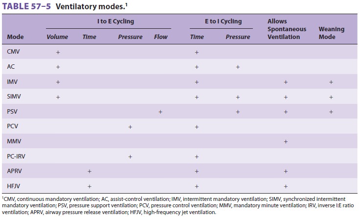
Ventilatory Modes
Ventilatory mode is defined by the method by which the ventilator cycles
from expiration to inspiration as well as whether the patient is able to
breathe spon-taneously (Table 57–5 and Figure
57–1). Most mod-ern ventilators are capable of multiple ventilatory modes,
and some (microprocessor-controlled venti-lators) can combine modes
simultaneously. Typical ventilatory modes are regulated to deliver a defined VT
or a defined maximal inspiratory pressure. Mod-ern ventilators can provide for
breaths that are vol-ume-controlled (machine-initiated inspiration stops when
the set volume is delivered), volume-assisted (patient-initiated inspiration
stops when the set volume is delivered), pressure-controlled (machine-initiated
inspiration at a mandatory inspiratory pressure stops after a defined time has
elapsed), pressure-assisted (patient-initiated inspiration at a mandatory
inspiratory pressure stops after a defined time has elapsed), or
pressure-supported (patient-initiated inspiration continues at a mandatory
inspi-ratory pressure until the inspiratory flow declines to a defined value).
A. Continuous Mandatory Ventilation (CMV)
In this mode, the ventilator cycles from
expiration to inspiration after a fixed time interval. The inter-val determines
the ventilatory rate. Typical settings on this mode provide a fixed VT and
fixed rate (and, therefore, minute ventilation) regardless of patient effort,
because the patient cannot breathe
spontane-ously. Settings to limit inspiratory pressure guardagainst
pulmonary barotrauma, and indeed CMV can be provided in a pressure-limited
(rather than volume-limited) way. Controlled ventilation is best reserved for
patients capable of little or no ventilatory effort. Awake patients with active
ventilatory effort require sedation, possibly with muscle paralysis.
B. Assist-Control (AC) Ventilation
Incorporation of a pressure sensor in the breathing circuit of AC ventilators permits the patient’s inspiratory effort to be used to trigger inspiration.
A sensitivity control allows selection of the inspira-tory effort
required. The ventilator can be set for a fixed ventilatory rate, but each
patient effort of sufficient magnitude will trigger the set VT. If spon-taneous
inspiratory efforts are not detected, the machine functions as if in the
control mode. Most often, AC ventilation is used in a volume-limited format,
but it can also be provided in a pressure-limited way .
C. Intermittent Mandatory Ventilation (IMV)
IMV allows spontaneous ventilation while the patient is on the
ventilator. A selected number of mechanical breaths (with fixed VT) is given to
supplement spontaneous breathing. At high man-datory rates (10–12 breaths/min),
IMV essentially provides all of the patient’s ventilation; at low rates (1–2
breaths/min), it provides minimal mechani-cal ventilation and allows the
patient to breathe relatively independently. The VT and frequency of spontaneous
breaths are determined by the patient’s ventilatory drive and muscle strength.
The IMV rate can be adjusted to maintain a desired minute ventilation. IMV has
found greatest use as a weaning technique.
Synchronized intermittent mandatory ventila-tion (SIMV) times the
mechanical breath, whenever possible, to coincide with the beginning of a
spon-taneous effort. Proper synchronization prevents superimposing (stacking) a
mechanical breath in the middle of a spontaneous breath, resulting in a very
large VT. As with CMV and AC, settings to limit inspiratory pressure guard
against pulmonary baro-trauma. The advantages of SIMV include patient comfort,
and if used for weaning, the machine breaths provide a backup if the patient
becomes fatigued. However, if the rate is too low (4 breaths/ min), the backup
may be too low, particularly for weak patients who may not be able to overcome
the added work of breathing during spontaneous breaths.
IMV circuits provide a continuous supply of gas flow for spontaneous ventilation between mechanical breaths. Modern ventilators incorporate SIMV into their design, but older models must be modified by a parallel circuit, a continuous flow system, or a demand flow valve. Regardless of the system, proper function-ing of one-way valves and sufficient gas flow are nec-essary to prevent an increase in the patient’s work of breathing, particularly when PEEP is also used.
The IMV discussion has considered this to be a volume-limited format;
however, it can also be pro-vided in pressure-limited format if desired .
D. Mandatory Minute Ventilation (MMV)
With MMV, the patient is able to breathe
sponta-neously (with pressure support) and also receive SIMV mechanical
breaths, while the machine moni-tors the exhaled minute ventilation. In this
mode, the machine continuously adjusts the number of SIMV mechanical breaths so
that the sum total of spontaneous and mechanical ventilation equals the desired
set minute ventilation. The role of this mode in weaning remains to be defined.
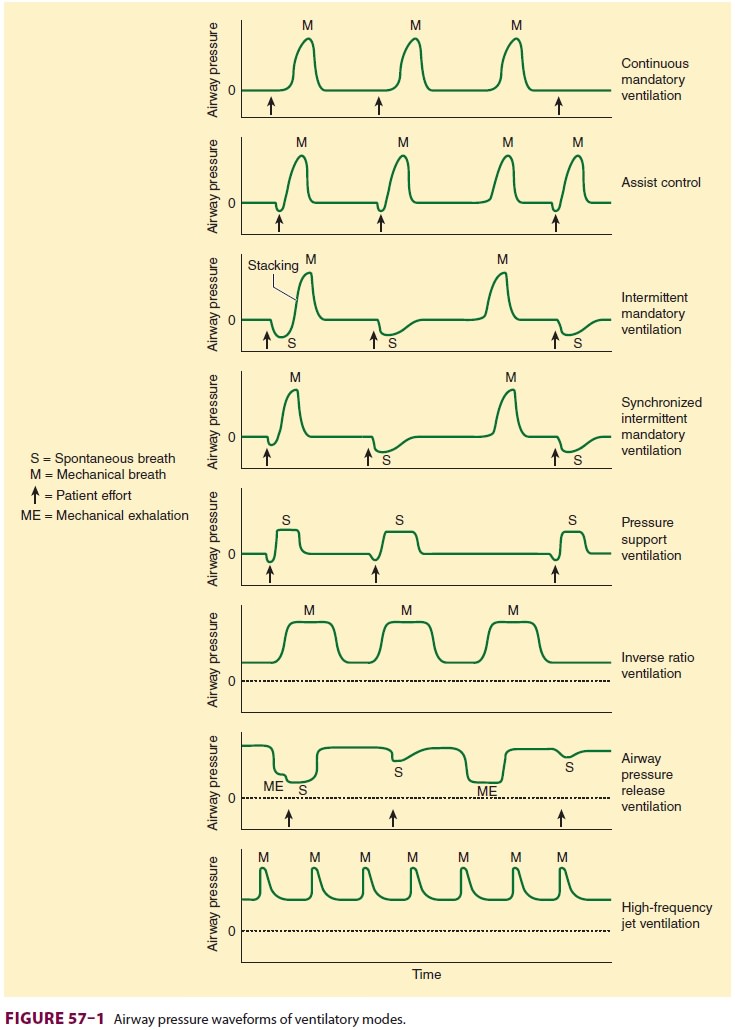
E. Pressure Support Ventilation (PSV)
Pressure support ventilation was designed to
aug-ment the VT of spontaneously breathing patients and overcome any increased
inspiratory resistance from the tracheal tube, breathing circuit (tubing,
connec-tors, and humidifier), and ventilator (pneumatic circuitry and valves).
Microprocessor-controlled machines have this mode, which delivers sufficient
gas flow with every inspiratory effort to maintain a predetermined positive
pressure throughout inspi-ration. When inspiratory flow decreases to a
prede-termined level, the ventilator’s feedback (servo) loop cycles the machine
into the expiratory phase, and air-way pressure returns to baseline (Figure
57–2). The only setting in this mode is inspiratory
pressure. The patient determines the respiratory rate and VT var-ies according
to inspiratory gas flow, lung mechan-ics, and the patient’s own inspiratory
effort. Low levels of PSV (5–10 cm H2O) are usually sufficient to overcome any added resistance imposed by
the breathing apparatus. Higher levels (10–40 cm H2O) can function as a standalone ventilatory mode if the patient has
sufficient spontaneous ventilatory drive and stable lung mechanics. The
principal advantages of PSV are its ability to augment spontaneous VT, decrease
the work of breathing, and increase patient comfort. However, if the patient
fatigues or lung mechanics change, VT may be inadequate, and there
is no backup rate if the patient’s intrinsic
respiratory rate decreases or the patient becomes apneic. Pres-sure support is
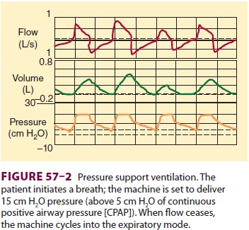
often used in conjunction with IMV (Figure 57–3).
The IMV machine breaths provide backup, and a low level of pressure support is
used to offset the increased work of breathing resulting from the breathing
circuit and machine.
F. Pressure Control Ventilation (PCV)
Pressure control ventilation is similar to PSV in that peak airway pressure is controlled butis different in that a mandatory rate and inspiratory time are selected. As with pressure support, gas flow ceases when the pressure level is reached; however, the ventilator does not cycle to expiration until the preset inspiration time has elapsed. PCV may be used in both the AC and IMV modes. In AC, all breaths (either machine initiated or patient initi-ated) are time cycled and pressure limited. In IMV, machine-initiated breaths are time cycled and pres-sure limited. The patient may breathe spontaneously between the set rate, and the VT of the spontaneous breaths is determined by the patient’s pulmonary muscle strength. The advantage of PCV is that by limiting inspiratory pressure, the risks of baro-trauma and volutrauma may be decreased. Also, by extending inspiratory time, better mixing and recruitment of collapsed or flooded alveoli may be achieved, provided adequate PEEP levels are used.
The disadvantage of conventional PCV is that
VT is not guaranteed (although there aremodes
in which the consistent delivered pressure of PCV can be combined with a
predefined volume delivery). Any change in compliance or resistance will affect
the delivered VT. This is a major issue in patients with acute lung injury
because if the com-pliance decreases and the pressure limit is not increased,
adequate VT may not be attained. PCV has been used for patients with acute lung
injury or ARDS, often with a prolonged inspiratory time or inverse I:E ratio
ventilation (IRV) in an effort to
recruit collapsed and flooded alveoli. The disadvantage of using IRV with PCV
is that the patient needs to be heavily sedated and often para-lyzed to
tolerate this particular ventilatory mode.
With PCV, pressure and inspiratory time are preset, whereas airflow and
volume are variable and dependent on the patient’s resistance and compli-ance.
With volume ventilation, on the other hand, inspiratory time is also preset but
flow and VT are also preset, and in this circumstance the inspiratory pressure
can be very high.
G. Inverse I:E Ratio Ventilation (IRV)
IRV reverses the normal inspiratory:expiratory time ratio of 1:3 or greater to a ratio of greater than 1:1. This may be achieved by adding an end-inspiratory pause, by decreasing peak inspiratory flow during volume-cycled ventilation (CMV), or by setting an inspiratory time such that inspiration is longer than expiration during PCV (PC-IRV). Intrinsic PEEP may be produced during IRV and is caused by air trapping or incomplete emptying of the lung to the baseline pressure prior to the initiation of the next breath. This air trapping increases FRC until a new equilibrium is reached. This mode does not allow spontaneous breathing and requires heavy seda-tion or neuromuscular blockade. IRV with PEEP is effective for improving oxygenation in patients with decreased FRC.
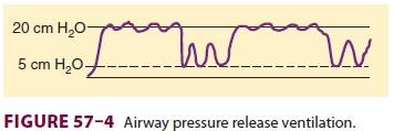
H. Airway Pressure Release Ventilation (APRV)
APRV or bilevel ventilation is a mode in
which a relatively high PEEP is used, despite the patient being allowed to
breathe spontaneously. Intermit-tently, the PEEP level decreases to help
augment the elimination of CO2 (Figure 57–4). The inspiratory and
expiratory times, high and low PEEP levels, and spontaneous respiratory
activity determine minute ventilation. Initial settings include a minimum PEEP
of 10–12 cm H2O
and a release level of 5–10 cm H2O. Advantages of APRV appear to be less circulatory depression and
pulmonary barotrauma as well as less need for sedation. This technique appears
to be an attractive alternative to PC-IRV for overcoming problems with high
peak inspiratory pressures in patients with reduced lung compliance.
I. High-Frequency Ventilation (HFV)
Three forms of HFV are available.
High-frequency positive-pressure ventilation involves delivering a small
“conventional” VT at a rate of 60–120 breaths/ min. High-frequency jet
ventilation (HFJV) utilizes a small cannula at or in the airway through which a
pulsed jet of high-pressure gas is delivered at a set frequency of 120–600
times/min (2–10 Hz). The jet of gas may entrain air (Bernoulli effect), which
may augment VT. High-frequency oscillation employs a driver (usually a piston)
that creates to-and-fro gas movement in the airway at rates of 180–3000 times/
min (3–50 Hz).
These forms of ventilation all produce VT at or below anatomic dead
space. The exact mecha-nism of gas exchange is unclear but is probably a
combination of effects (including convective ven-tilation, asymmetrical
velocity profiles, Taylor dispersion, pendelluft, molecular diffusion, and
cardiogenic mixing). Jet ventilation has found wid-est use in the operating
room. It may be used for laryngeal, tracheal, and bronchial procedures and can
be lifesaving in emergency airway manage-ment when tracheal intubation and
conventional positive-pressure ventilation are unsuccessful . In the ICU, HFJV
may be useful in managing some patients with bronchopleural and
tracheoesophageal fistulas when conventional ven-tilation has failed.
Occasionally, HFJV or high-fre-quency oscillation is used in patients with ARDS
to try to improve oxygenation. Inadequate heating and humidification of
inspired gases during pro-longed HFV, however, can be a problem. Initial
set-tings for HFJV in the operating room are typically a rate of 120–240
breaths/min, an inspiratory time of 33%, and a drive pressure of 15–30 psi.
Mean airway pressure should be measured in the trachea at least 5 cm below the
injector to avoid an artifac-tual error from gas entrainment. Carbon dioxide
elimination is generally increased by increasing the drive pressure, whereas
adequacy of oxygenation relates to the mean airway pressure. An intrinsic PEEP
effect is seen during HFJV at high drive pres-sures and inspiratory times
greater than 40%.
J. Differential Lung Ventilation
This technique, also referred to as
independent lung ventilation, may be used in patients with severe uni-lateral
lung disease or those with bronchopleural fistulae. Use of conventional
positive-pressure ven-tilation and PEEP in such instances can aggravate
ventilation/perfusion mismatching or, in patients with fistula, result in
inadequate ventilation of the unaffected lung. In patients with restrictive
disease of one lung, overdistention of the normal lung can lead to worsening
hypoxemia or barotrauma. After separation of the lungs with a double-lumen
tube, positive-pressure ventilation can be applied to each lung independently
using two ventilators. When two ventilators are used, the timing of mechanical
breaths is often synchronized, with one ventilator, the “master,” setting the
rate for the “slave” ventilator.
Related Topics