Chapter: Embedded Systems Design : Real-time operating systems
Multitasking operating systems
Multitasking operating systems
For the majority of embedded systems, a single tasking operating system
is too restrictive. What is required is an operat-ing system that can run
multiple applications simultaneously and provide intertask control and
communication. The facilities once only available to mini and mainframe
computer users are now required by 16/32 bit microprocessor users.
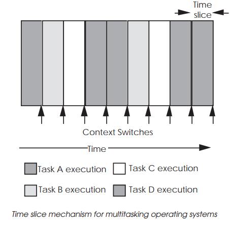
A multitasking operating system works by dividing the processor’s time
into discrete time slots. Each application or task requires a certain number of
time slots to complete its execution. The operating system kernel decides which
task can have the next slot, so instead of a task executing continuously until
completion, its execution is interleaved with other tasks. This sharing of
processor time between tasks gives the illusion to each user that he is the only
one using the system.
Context switching, task tables, and kernels
Multitasking operating systems are based around a multitasking kernel
which controls the time slicing mechanisms. A time slice is the time period
each task has for execution before it is stopped and replaced during a context
switch. This is periodi-cally triggered by a hardware interrupt from the system
timer. This interrupt may provide the system clock and several inter-rupts may
be executed and counted before a context switch is performed.
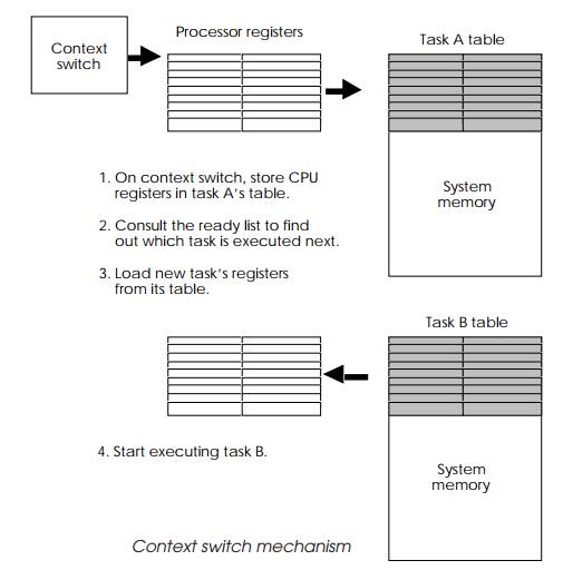
When a context switch is performed, the current task is interrupted, the
processor’s registers are saved in a special table for that particular task and
the task is placed back on the ‘ready’ list to await another time slice.
Special tables, often called task control blocks, store all the information the
system requires about the task, for example its memory usage, its priority
level within the system and its error handling. It is this context information
that is switched when one task is replaced by another.
The ‘ready’ list contains all the tasks and their status and is used by
the scheduler to decide which task is allocated the next time slice. The
scheduling algorithm determines the sequence and takes into account a task’s
priority and present status. If a task is waiting for an I/O call to complete,
it will be held in limbo until the call is complete.
Once a task is selected, the processor registers and status at the time
of its last context switch are loaded back into the processor and the processor
is started. The new task carries on as if nothing had happened until the next
context switch takes place. This is the basic method behind all multitasking
operating systems.
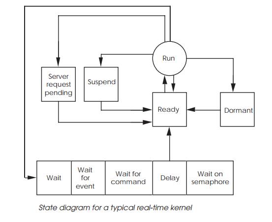
The diagram shows a simplified state diagram for a typical real-time
operating system which uses this time slice mechanism. On each context switch,
a task is selected by the kernel’s scheduler from the ‘ready’ list and is put
into the run state. It is then executed until another context switch occurs.
This is normally signalled by a periodic interrupt from a timer. In such cases
the task is simply switched out and put back on the ‘ready’ list, awaiting its
next slot. Alternatively, the execution can be stopped by the task executing
certain kernel commands. It could suspend itself, where it remains present in
the system but no further execution occurs. It could become dormant, awaiting a
start command from another task, or even simply waiting for a server task
within the operating system to perform a special function for it. A typical
example of a server task is a driver performing special screen graphics
functions. The most common reason for a task to come out of the run state, is
to wait for a message or command, or delay itself for a certain time period.
The various wait directives allow tasks to synchronise and control each other
within the system. This state diagram is typical of many real-time operating
systems.
The kernel controls memory usage and prevents tasks from corrupting each
other. If required, it also controls memory sharing between tasks, allowing
them to share common program mod-ules, such as high level language run-time
libraries. A set of memory tables is maintained, which is used to decide if a
request is accepted or rejected. This means that resources, such as physical
memory and peripheral devices, can be protected from users without using
hardware memory management provided the task is disciplined enough to use the
operating system and not access the resources directly. This is essential to
maintain the system’s integrity.
Message passing and control can be implemented in such systems by using
the kernel to act as a message passer and controller between tasks. If task A
wants to stop task B, then by executing a call to the kernel, the status of
task B can be changed and its execution halted. Alternatively, task B can be
delayed for a set time period or forced to wait for a message.
With a typical real-time operating system, there are two basic type of
messages that the kernel will deal with:
•
flags that can control but cannot
carry any implicit informa-tion — often called semaphores or events and
•
messages which can carry
information and control tasks — often called messages or events.
The kernel maintains the tables required to store this infor-mation and
is responsible for ensuring that tasks are controlled and receive the
information. With the facility for tasks to commu-nicate between each other,
system call support for accessing I/O, loading tasks from disk etc., can be
achieved by running addi-tional tasks, with a special system status. These
system tasks provide additional facilities and can be included as required.
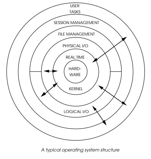
To turn a real-time kernel into a full operating system with file systems
and so on, requires the addition of several such tasks to perform I/O services,
file handling and file management serv-ices, task loading, user interface and
driver software. What was about a small <16 kbyte-sized kernel will often
grow into a large 120 kbyte operating system. These extra facilities are built
up as layers surrounding the kernel. Application tasks then fit around the
outside. A typical onion structure is shown as an example. Due to the modular
construction, applications can generally access any level directly if required.
Therefore, application tasks that just require services provided by the kernel
can be developed and debugged under the full environment, and stripped down for
integration onto the target hardware.
In a typical system, all these service tasks and applications are
controlled, scheduled and executed by the kernel. If an appli-cation wishes to
write some data to a hard disk in the system, the process starts with the
application creating a parameter block and asking the file manager to open the
file. This system call is normally executed by a TRAP instruction. The kernel
then places the task on its ‘waiting’ list until the file manager had finished
and passed the status information back to the application task. Once this event
has been received, it wakes up and is placed on the ‘ready’ list awaiting a
time slot.
These actions are performed by the kernel. The next appli-cation command
requests the file handling services to assign an identifier — often called a
logical unit number (LUN) — to the file prior to the actual access. This is
needed later for the I/O services call. Again, another parameter block is
created and the file handler is requested to assign the LUN. The calling task
is placed on the ‘waiting’ list until this request is completed and the LUN
returned by the file handler. The LUN identifies a particular I/O resource such
as a serial port or a file without actually knowing its physical
characteristics. The device is therefore described as logical rather than
physical.
With the LUN, the task can create another parameter block, containing
the data, and ask the I/O services to write the data to the file. This may
require the I/O services to make system calls of its own. It may need to call
the file services for more data or to pass further information on. The data is
then supplied to the device driver which actually executes the instructions to
physically write the data to the disk. It is generally at this level that the
logical nature of the I/O request is translated into the physical
character-istics associated with the hardware. This translation should lie in
the domain of the device driver software. The user application is unaware of
these characteristics.
A complex system call can cause many calls between the system tasks. A
program loader that is requested by an application task to load another task
from memory needs to call the file services and I/O services to obtain the file
from disk, and the kernel to allocate memory for the task to be physically
loaded.
The technique of using standard names, files, and/or logi-cal unit
numbers to access system I/O makes the porting of application software from one
system to another very easy. Such accesses are independent of the hardware the
system is running on, and allow applications to treat data received or sent in
the same way, irrespective of its source.
What is a real-time operating
system?
Many multitasking operating systems available today are also described
as ‘real-time’. These operating systems provide additional facilities allowing
applications that would normally interface directly with the microprocessor
architecture to use interrupts and drive peripherals to do so without the
operating system blocking such activities. Many multitasking operating systems
prevent the user from accessing such sensitive resources. This overzealous
caring can prevent many operating systems from being used in applications such
as industrial control.
A characteristic of a real-time operating system is its de-fined
response time to external stimuli. If a peripheral generates an interrupt, a
real-time system will acknowledge and start to service it within a maximum
defined time. Such response times vary from system to system, but the maximum
time specified is a worst case figure, and will not be exceeded due to changes
in factors such as system workload.
Any system meeting this requirement can be described as real-time,
irrespective of the actual value, but typical industry accepted figures for
context switches and interrupt response times are about 10 microseconds. This
figure gets smaller as processors become more powerful and run at higher
speeds. With several processors having the same context switch mechanism, the
final context switch time come down to its clock speed and the memory access
time.
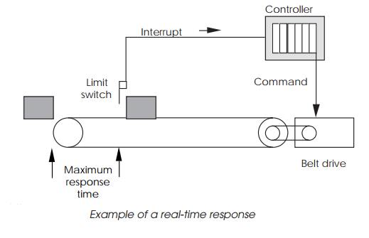
The consequences to industrial control of not having a real-time
characteristic can be disastrous. If a system is controlling an automatic
assembly line, and does not respond in time to a request from a conveyor belt
limit switch to stop the belt, the results are easy to imagine. The response
does not need to be instantaneous
— if the limit switch is set so that there are 3 seconds to stop the
belt, any system with a guaranteed worst case response of less than 3 seconds
can meet this real-time requirement.
For an operating system to be real-time, its internal mecha-nisms need
to show real-time characteristics so that the internal processes sequentially
respond to external interrupts in guaran-teed times.
When an interrupt is generated, the current task is inter-rupted to
allow the kernel to acknowledge the interrupt and obtain the vector number that
it needs to determine how to handle it. A typical technique is to use the
kernel’s interrupt handler to update a linked list which contains information
on all the tasks that need to be notified of the interrupt.
If a task is attached to a vector used by the operating system, the
system actions its own requirements prior to any further response by the task.
The handler then sends an event message to the tasks attached to the vector,
which may change their status and completely change the priorities of the task
ready list. The scheduler analyses the list, and dispatches the highest
priority task to run. If the interrupt and task priorities are high enough,
this may be the next time slice.
The diagram depicts such a mechanism: the interrupt han-dler and linked
list searches are performed by the kernel. The first priority is to service the
interrupt. This may be from a disk controller indicating that it has completed
a data transfer. Once the kernel has satisfied its own needs, the handler will
start a linked list search. The list comprises blocks of data identifying tasks
that have their own service routines. Each block will contain a refer-ence to
the next block, hence the linked list terminology.
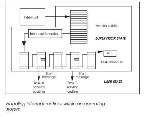
Each identified task is then sent a special message. This will start the
task’s service routine when it receives its next time slice. The kernel
interrupt handler will finally execute an RTE return from the exception
instruction which will restore the processor state prior to the interrupt. In
such arrangements the task service routines execute in USER mode. The only
SUPERVISOR operation is that of the kernel and its own interrupt handler. As
can be imagined, this processing can increase the interrupt latency seen by the
task quite dramatically. A ten-fold increase is not uncom-mon.
To be practical, a real-time operating system has to guaran-tee maximum
response times for its interrupt handler, event passing mechanisms, scheduler
algorithm and provide system calls to allow tasks to attach and handle
interrupts.
With the conveyor belt example above, a typical software configuration
would dedicate a task to controlling the conveyor belt. This task would make
several system calls on start-up to access the parallel I/O peripheral that
interfaces the system to components such as the drive motors and limit switches
and tells the kernel that certain interrupt vectors are attached to the task
and are handled by its own interrupt handling routine.
Once the task has set everything up, it remains dormant until an event
is sent by other tasks to switch the belt on or off. If a limit switch is
triggered, it sets off an interrupt which forces the kernel to handle it. The
currently executing task stops, the kernel handler searches the task interrupt
attachment linked list, and places the controller task on the ready list, with
its own handler ready to execute. At the appropriate time slice, the handler
runs, accesses the peripheral and switches off the belt. This result may not be
normal, and so the task also sends event messages to the others, informing them
that it has acted independently and may force other actions. Once this has been
done, the task goes back to its dormant state awaiting further commands.
Real-time operating systems have other advantages: to prevent a system
from power failure usually needs a guaranteed response time so that the short time
between the recognition of and the actual power failure can be used to store
vital data and bring the system down in a controlled manner. Many operating
systems actually have a power fail module built into the kernel so that no time
is lost in executing the module code.
So far in this chapter, an overview of the basics behind a real-time
operating system have been explained. There are, how-ever, several variants
available for the key functions such as task swapping and so on. The next few
sections will delve deeper into these topics.
Task swapping methods
The choice of scheduler algorithms can play an important part in the
design of an embedded system and can dramatically affect the underlying design
of the software. There are many different types of scheduler algorithm that can
be used, each with either different characteristics or different approaches to
solving the same problem of how to assign priorities to schedule tasks so that
correct operation is assured.
Time slice
Time slicing has been previously mentioned in this chapter under the
topic of multitasking and can be used within an embed-ded system where time
critical operations are not essential. To be more accurate about its
definition, it describes the task switching mechanism and not the algorithm
behind it although its meaning has become synonymous with both.
Time slicing works by making the task switching regular periodic points
in time. This means that any task that needs to run next will have to wait
until the current time slice is completed or until the current task suspends
its operation. This technique can also be used as a scheduling method as will
be explained later in this chapter. The choice of which task to run next is
determined by the scheduling algorithm and thus is nothing to do with the time
slice mechanism itself. It just happens that many time slice-based systems use
a round-robin or other fairness scheduler to distribute the time slices across
all the tasks that need to run.
For real-time systems where speed is of the essence, the time slice
period plus the context switch time of the processor deter-mines the context
switch time of the system. With most time slice periods in the order of
milliseconds, it is the dominant factor in the system response. While the time
period can be reduced to improve the system context switch time, it will
increase the number of task switches that will occur and this will reduce the
efficiency of the system. The larger the number of switches, the less time
there is available for processing.
Pre-emption
The alternative to time slicing is to use pre-emption where a currently
running task can be stopped and switched out — pre-empted — by a higher
priority active task. The active qualifier is important as the
example of pre-emption later in this section will show. The main difference is
that the task switch does not need to wait for the end of a time slice and
therefore the system context switch is now the same as the processor context
switch.
As an example of how pre-emption works, consider a system with two tasks
A and B. A is a high priority task that acts as an ISR to service a peripheral
and is activated by a processor interrupt from the peripheral. While it is not
servicing the periph-eral, the task remains dormant and stays in a suspended state.
Task B is a low priority task that performs system housekeeping.
When the interrupt is recognised by the processor, the operating system
will process it and activate task A. This task with its higher priority
compared to task B will cause task B to be pre-empted and replaced by task A.
Task A will continue processing until it has completed and then suspend itself.
At this point, task B will context switch task A out because task A is no
longer active.
This can be done with a time slice mechanism provided the interrupt rate
is less than the time slice rate. If it is higher, this can also be fine
provided there is sufficient buffering available to store data without losing
it while waiting for the next time slice point. The problem comes when the interrupt
rate is higher or if there are multiple interrupts and associated tasks. In
this case, multiple tasks may compete for the same time slice point and the
ability to run even though the total processing time needed to run all of them
may be considerably less than the time provided within a single time slot. This
can be solved by artificially creating more context switch points by getting
each task to suspend after com-pletion. This may offer only a partial solution
because a higher priority task may still have to wait on a lower priority task
to complete. With time slicing, the lower priority task cannot be pre-empted
and therefore the higher priority task must wait for the end of the time slice
or the lower priority task to complete. This is a form of priority inversion
which is explained in more detail later.
Most real-time operating systems support pre-emption in preference to
time slicing although some can support both meth-odologies
Co-operative multitasking
This is the mechanism behind Windows 3.1 and while not applicable to
real-time operating systems for reasons which will become apparent, it has been
included for reference.
The idea of co-operative multitasking is that the tasks themselves
co-operate between themselves to provide the illusion of multitasking. This is
done by periodically allowing other tasks or applications the opportunity to
execute. This requires program ming within the application and the system can
be destroyed by a single rogue program that hogs all the processing power. This
method may be acceptable for a desktop personal computer but it is not reliable
enough for most real-time embedded systems.
Related Topics