Chapter: Embedded Systems Design : Real-time operating systems
Memory model
Memory model
The memory model that the processor offers can and often varies with the
model defined by the operating system and is open to the software designer to
use. In other words, although the processor may support a full 32 bit address
range with full memory mapped I/O and read/write access anywhere in the map at
a level of an individual word or map, the operating system’s representation of
the memory map may only be 28 bits, with I/O access allocated on a 512 byte
basis with read only access for the first 4 Mbytes of RAM and so on.
This discrepancy can get even wider, the further down in the levels that
you go. For example, most processors that have sophisticated cache memory
support use the memory manage-ment unit. This then requires fairly detailed
information about the individual memory blocks within a system. This
information has to be provided to the RTOS and is normally done using various
memory allocation techniques where information is provided when the system
software is compiled and during operation.
Memory allocation
Most real-time operating systems for processors where the memory map can
be configured, e.g. those that have large memory addressing and use memory
mapped I/O, get around this prob-lem by using a special file that defines the
memory map that the system is expected to use and support. This will define
which memory addresses correspond to I/O areas, RAM, ROM and so on. When a task
is created, it will be given a certain amount of memory to hold its code area
and provide some initial data storage. If it requires more memory, it will
request it from the RTOS using a special call such as malloc(). The RTOS will
look at the memory request and allocate memory by passing back a pointer to the
additional memory. The memory request will normally define the memory
characteristics such as read/write access, size, and even its location and
attributes such as physical or logical addressing.
The main question that arises is why dynamically allocate memory? Surely
this can be done when the tasks are built and included with the operating system?
The answer is not straightfor-ward. In simple terms, it is a yes and for many
simple embedded systems, this is correct. For more complex systems, however,
this static allocation of memory is not efficient, in that memory may be
reserved or allocated to a task yet could only be used rarely within the
system’s operation. By dynamically allocating memory, the total amount of
memory that the system requires for a given function can be reduced by
reclaiming and reallocating memory as and when needed by the system software.
This will be ex-plained in more detail later on.
Memory characteristics
The memory characteristics are important to understand especially when
different memory addresses correspond to differ-ent physical memory. As a
result, asking for a specific block of memory may impact the system
performance. For example, con-sider an embedded processor that has both
internal and external memory. The internal memory is faster than the external
memory and therefore improves performance by not inserting wait states during a
memory access. If a task asks for memory expecting to be allocated internal
memory but instead receives a pointer to exter-nal memory, the task performance
will be degraded and poten-tially the system can fail. This is not a programming
error in the true sense of the word because the request code and RTOS have
executed correctly. If the request was not specific enough, then the receiving
task should expect the worst case type of memory. If it does not or needs
specific memory, this should be specified during the request. This is usually
done by specifying a memory address or type that the RTOS memory allocation
code can check against the memory map file that was used when the system was
built.
•
Read/write access
This is straightforward and defines the access permissions that a task
needs to access a memory block.
•
Internal/external memory
This is normally concerned with speed and performance issues. The
different types of memory are normally defined not by their speed but
indirectly through the address loca-tion. As a result, the programmer must
define and use a memory map so that the addresses of the required memory block
match up the required physical memory and thus its speed. Some RTOSs actually
provide simple support flags such as internal/external but this is not common.
•
Size
The minimum and maximum sizes are system dependent and typically are
influenced by the page size of any memory management hardware that may be
present. Some systems can return with partial blocks, e.g. if the original
request was for 8 kbytes, the RTOS may only have 4 kbytes free and instead of
returning an error, will return a pointer to the 4 kbytes block instead. This
assumes that the requesting task will check the returned size and not simply
assume that because there was no error, it has all the 8 kbytes it re-quested!
Check the RTOS details carefully.
•
I/O
This has several implications when using processors that execute
instructions out of order to remove pipeline stalls and thus gain performance.
Executing instructions that access I/O ports out of sequence can break the
program syntax and integrity. The program might output a byte and then read a
status register. If this is reversed, the correct sequence has been destroyed
and the software will prob-ably crash. By declaring I/O addresses as I/O, the
proces-sor can be programmed to ensure the correct sequence whenever these
addresses are accessed.
•
Cached or non-cachable
This is similar to the previous paragraph on I/O. I/O addresses should
not be cached to prevent data corruption. Shared memory blocks need careful
handling with caches and in many cases unless there is some form of bus
snoop-ing to check that the contents of a cache is still valid, these areas
should also not be cached.
•
Coherency policies
Data caches can have differing coherency policies such as write-through,
copy back and so on which are used to ensure the data coherency within the
system. Again, the ability to specify or change these policies is useful.
Example memory maps
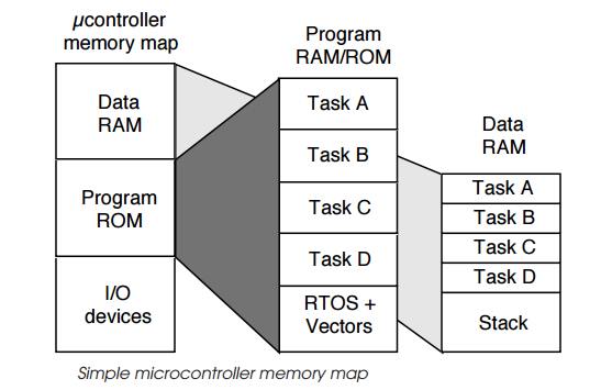
The first example is that commonly used within a simple microcontroller
where its address space is split into the different memory types. The example
shows three: I/O devices and periph-erals, program RAM and ROM and data RAM.
The last two types have then been expanded to show how they could be allocated
to a simple embedded system. The program area contains the code for four tasks,
the RTOS code and the processor vector table. The data RAM is split into five
areas: one for each of the tasks and a fifth area for the stack. In practice,
these areas are often further divided into internal and external memory, EPROM
and EEPROM, SRAM and even DRAM, depending on the processor architecture and
model. This example uses a fixed static memory map where the memory requirements
for the whole system are defined at com-pile and build time. This means that
tasks cannot get access to additional memory by using some of the memory
allocated to another task. In addition, it should be remembered that although
the memory map shows nicely partitioned areas, it does not imply nor should it
be assumed that task A cannot access task C’s data area, for example. In these
simple processors and memory maps, all tasks have the ability to access any
memory location and it is only the correct design and programming that ensures
that there is no corruption. Hardware can be used to provide this level of
protection but it requires some form of memory management unit to check that
programs are conforming to their design and not accessing memory that they should
not. Memory management is explained in some detail in the next section.
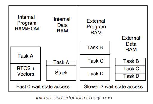
The second example shows a similar system to the first example except
that it has been further partitioned into internal and external memory. The
internal memory runs faster than the external memory and because it does not
have any wait states, its access time is faster and the processor performance
does not degrade. The slower external memory has two wait states and with a
single cycle processor would degrade performance by 66% each instruction would
take three clocks instead of one, for example.
Given this performance difference, it is important that the memory
resources are carefully allocated. In the example, task A requires the best
performance and the system needs fast task switching. This means that both the
task A code and data, along with the RTOS and the system stack, are allocated
to the internal memory where it will get the best performance. All other task
code and data are stored externally because all the internal memory is used.
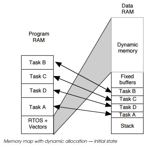
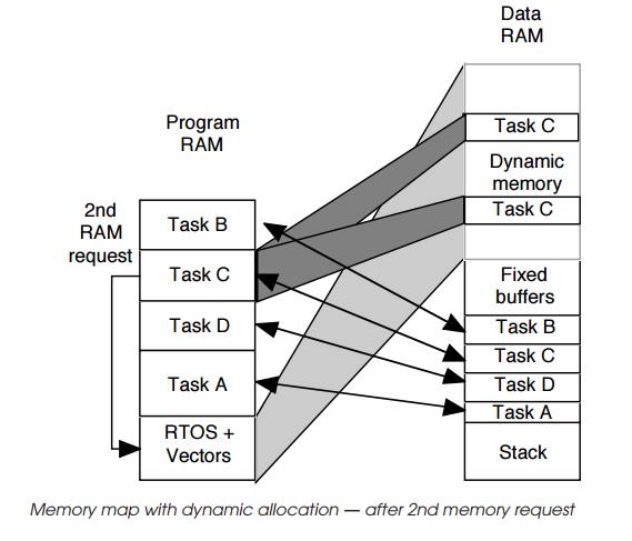
The third example shows a dynamic allocation system where tasks can
request additional memory as and when they need it. The first map shows the
initial state with the basic memory allocated to tasks and RTOS. This is
similar to the previous examples except that there is a large amount of memory
entitled to dynamic memory which is controlled by the RTOS and can be allocated
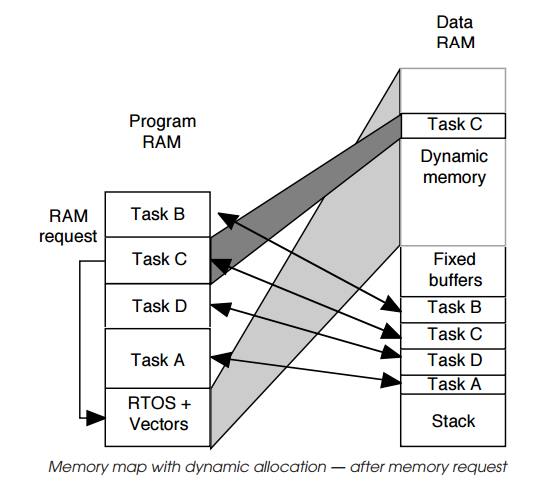
dynamically by it to other tasks on demand. The next two diagrams show this in
operation. The first request by task C starts by sending a request to the RTOS
for more memory. The RTOS allocates a block to the task and returns a pointer
to it. Task C can use this to get access to this memory. This can be repeated
if needed and the next diagram shows task C repeating the request and getting
access to a second block. Blocks can also be relin-quished and returned to the
RTOS for allocation to other tasks at some other date. This process is highly
dynamic and thus can provide a mechanism for minimising memory usage. Task C
could be allocated all the memory at certain times and as the memory is used
and no longer required, blocks can be reallocated to different tasks.
The problem with this is in calculating the minimum amount of memory
that the system will require. This can be difficult to estimate and many
designs start with a large amount of memory, get the system running and then
find out empirically the mini-mum amount of required memory.
In this section, the use of memory management within an embedded design
has been alluded to in the case of protecting memory for corruption. While this
is an important use, it is a secondary advantage compared to its ability to
reuse memory through address translation. Before returning to the idea of
memory protection, let’s consider how address translation works and affects the
memory map.
Related Topics