Chapter: Mechanical : Robotics : Robot Drive Systems and End Effectors
Mechanical drives system
Mechanical
drives system
When the various
driving methods like hydraulic, pneumatic, electrical servo motors and stepping
motors are used in robots, it is necessary to get the motion in linear or
rotary fashion.
When motors are used,
rotary motion is converted to linear motion through rack and pinion gearing,
lead screws, worm gearing or bail screws.
Rack
and Pinion Movement:
The pinion is in mesh
with rack (gear of infinite radius). If the rack is fixed, the pinion will
rotate. The rotary motion of the pinion will be converted to linear motion of
the carriage.
Ball
Screws:
Sometimes lead screws
rotate to drive the nut along a track. But simple lead screws cause friction
and wear, causing positional inaccuracy.
Therefore ball bearing
screws are used in robots as they have low friction. The balls roll between the
nut and the screw. A cage is provided for recirculation of the balls. The
rolling friction of the ball enhances transmission efficiency to about 90%.
Gear
Trains:
Gear trains use spur,
helical and worm gearing. A reduction of speed, change of torque and angular
velocity are possible. Positional errors are caused due to backlash in the
gears.
Harmonic Drive:
For
speed reduction, standard gear transmission gives sliding friction and
backlash.
Moreover,
it takes more space.
Harmonic drive due to
its natural preloading eliminates backlash and greatly reduces tooth wear.
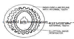
Harmonic drives are suitable for robot
drives due to their smooth and efficient action. The circular spline is a rigid
ring with gear teeth machined on the inside diameter.
The
flex spline is a flexible ring with the teeth cut on its outside diameter.
The flex spline has
fewer teeth (say 2 teeth less) than the circular spline. The wave generator is
elliptical and is given input motion.
Wave generator and flex
spline is placed into the circular spline such that the outer tooth of flex
spline is in mesh with the internal teeth of circular spline.
If the circular spline
has 100 teeth and the flex spline has 98 teeth, and if the wave generator makes
one complete revolution, the flex spline will engage 98 teeth of the circular
spline.
Since circular spline
has 100 teeth and only 98 teeth have been in engagement for one complete
rotation, the circular saline's position has been shifted by 2 teeth.
Thus after 50
revolutions of the wave generator, the circular spline will have made one full
rotation. The ratio of harmonic drive is 2: 100 or 1: 50.
The gear ratio is influenced by the number of teeth
cut into the circular spline and the flex spline. The harmonic drive has high
torque capacity.
Related Topics