Chapter: Aquaculture Engineering : Heating and Cooling
Factors affecting heat transfer - Aquaculture Engineering
Factors affecting
heat transfer
The rate of energy transfer (P)
of the heat exchanger depends on the temperature difference between the media,
the thermal conductivity of the material in the heat exchanger and the area
over which the energy is transferred; it can be calculated from the equation
P = kA LMTD
where:
k = heat transfer coefficient (W/(m2 ┬░C))
A = heat transfer area (m2)
LMTD = log mean temperature difference (┬░C).
The value of k gives
the quantity of energy trans-ferred per square metre surface area and degree
temperature difference. Various factors affect k; in practice, values of up to 8 kW/(m2 ┬░C) are
achieved. kcan be calculated from the
following equation:

Here, a1 and a2 are the heat transfer coefficients
on each side of the material in the heat exchanger. They give the quantity of
energy transferred from a liquid or gas to or from unit area of a fixed
mate-rial and per degree temperature difference. The values depend on the
condition for convection and conduction and can be improved by optimizing
operational conditions.
tp is the thickness of the material that
separatesthe two flowing media; increasing tp
will decrease k because the heat must
be transported a greater dis-tance through the fixed material. Use of a thin
fixed material results in a low k
value.
l is the heat convection factor for the
material;steel and other metals have a high factor, while glass and plastics
have a lower factor. This why metal with good conductivity is used for the heat
transfer plates.
Rf is the fouling factor, which gives
the amountof fouling on the material of the heat transfer plates. Fouling
reduces k, and therefore the rate of
energy transfer will be reduced. High turbulence close to the surface of the
heat transfer plates will reduce the amount of fouling, in addition to improving
a1 and a2. Cleaning of the
exchange sur-faces will also reduce the fouling, Rf. The reduction in k
is because the conductivity of the layer of fouling is low and the thickness of
the transfer material is increased.
Manufacturers of heat exchangers normally give kA as a single value. This is because
each manufac-turer will have their own design for the heat transfer area to
create optimum flow with turbulence; to improve conditions for turbulence and
increase the heat transfer area, various patterns are used on the exchange
surface, including grooves and corrugations.
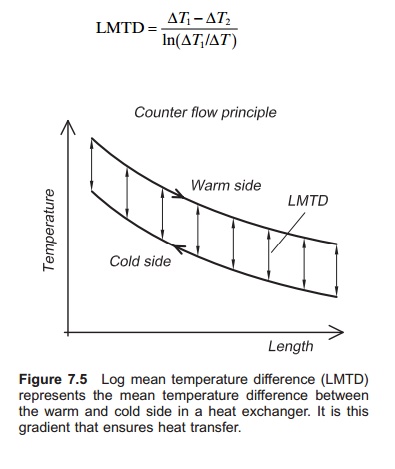
The temperature gradient between the warm and the cold side in
the exchanger (Fig. 7.5) ensures energy transfer. It is expressed as the LMTD.
A log-arithmetic expression is used because temperature equalization between
the media through the exchanger may not be linear. LMTD can be calcu-lated from
the following equation:

where:
T1=tin(hot water)ŌłÆ tout(heated water)
T2=tout(cooled water)ŌłÆ tin(water to be heated).
If the amount of water and the heat exchange area are the same
on both sides of the heat exchanger, ŌłåT1= ŌłåT2=LMTD. LMTD will vary depending onwhether it
is a parallel-flow
or counterflow exchanger.
Related Topics