Chapter: Aquaculture Engineering : Heating and Cooling
Composite heating systems - Aquaculture Engineering
Composite heating
systems
A composite heating system is normally used to heat water for
use in fish farming. The system comprises several components that all have some
heating effect on the inlet water. Usually there are one or several heat
exchangers in addition to either a heat pump on large farms, or a heater or an
oil burner on smaller farms. The COP is calculated for the entire heating
system and are usually in the range 15ŌĆō25, which means that for each kW of
electric energy supplied, the water is heated by 15ŌĆō25 kW. Examples given below
include heaters, heat pumps and heat exchangers to illustrate the profitability
of using a composite heating system.
Example
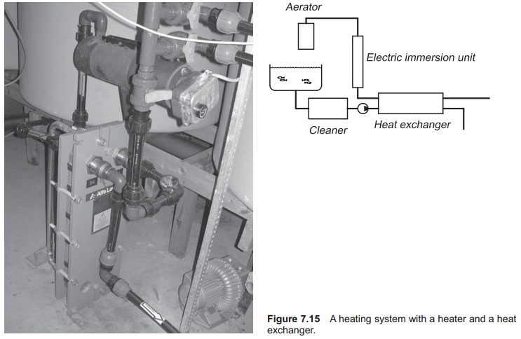
Heater and heat exchanger (Fig. 7.15)

Calculate the profitability of adding
a heat exchanger compared with using only an electric immersion heater in a
small heating system. A water flow of 180 l/min (3 l/s) is to be heated from 4 to 8┬░C. The first calculation is for an
electric heater alone.
Size of the heater:
P =mcpdt
= 3 l/s ├Ś 4.18 kJ/(kg ┬░C) ├Ś (8 ŌłÆ 4┬░C)
=50.2 kJ/s
=50.2 kW
The daily cost of using this system
with an electric-ity price of 0.1 Ōé¼/kWh is:
50.2 kW ├Ś 24 h ├Ś 0.1 Ōé¼/kWh = 120.5 Ōé¼
Now a heat exchanger is included in
the circuit to recover the energy in the outlet water; 75% recovery is quite
normal. This value of course depends on the cost of the heater, heat exchanger
and electricity; simu-lations should be done to find the most economical
combination. If 75% of the total heat increase above 4┬░C is provided by the
heat exchanger, 3┬░C of the temperature rise results from its use. This gives
the following temperatures in the heat exchanger as the same amount of water
flows on both sides:
Water entering heat exchanger 4┬░C
Water leaving heat exchanger 7┬░C
Water entering heater 7┬░C
Water leaving heater 8┬░C
A smaller heater is therefore needed
as the water is only going to be heated from 7 to 8┬░C:
P =3├Ś4.18├Ś(8ŌłÆ7)= 12.5 kW
This gives the following new daily
running costs:
12.5 ├Ś 24 ├Ś 0.1 = 30.0 Ōé¼
As can be seen, the daily cost of
heating is reduced from 120.5 to 30.0 Ōé¼, a saving of 90.5 Ōé¼ per day, by adding
a heat exchanger. This clearly illustrates the advantage of using a heat
exchanger.
The necessary size of the exchanger
will now be found.
Since the same amount of water is
circulating on both sides of the heat exchanger, it has the following
temperature programme:
Water entering heat exchanger 4┬░C
Water leaving heat exchanger 7┬░C
Water entering heater 7┬░C
Water leaving heater 8┬░C
The energy to be transferred from the
warm to the cold side in the heat exchanger given by
=
mcpdt
3 ├Ś 4.18 ├Ś 3
37.6 kJ/s
For a heat exchanger the following
equation applies:
P = kA LMTD
The k value for the plates in the
exchanger is set to 6 kW/(m2
┬░C) and the LMTD (temperature differ-ence that drives the heat transfer) is
1.0┬░C, which gives the following area:
=
P/(k LMTD)
=37.6/(6 ├Ś 1.0)
= 6.3 m2
Assuming a plate size of width 0.4 m
and height 1 m, the area is 0.4 m2 (this depends on the size of
plate supplied). The number of plates required = 6.3/0.4
= 15.8; this is an exchanger with 16 plates.
Example
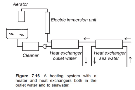
Heater with heat exchangers in outlet
water and in seawater (Fig. 7.16).

The inlet water has a temperature of
2┬░C and this is increased to 4┬░C when the water passes the seawater exchanger.
The water then enters an outlet exchanger where the temperature is further
increased to 9┬░C. The last increment up to 10┬░C, which is the temper-ature in
the fish tank, is supplied through an electric heater. Calculate the COP of the
system.
e = Qdeliverd/Qsupplied
= (ttankŌłÆtraw water)/(ttankŌłÆtbefore heater)
= (10 ŌłÆ 2)/(10 ŌłÆ 9)
= 8
The COP is 8 for this system, so that
for every kW of electric energy supplied 8 kW is supplied to the inlet water.
Example
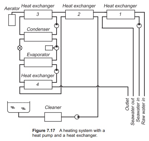
Heat pump and heat exchanger (Fig.
7.17)
Find the profitability of installing
a heat pump, com-pared with a total energy system including a heat pump and
heat exchangers. A water flow of 300 l/min (50 l/s) is to be heated from 2 to 8┬░C. The heat pump has a COP of 5. How
much electric energy must be supplied?

First, the total amount of energy
that has to be trans-ferred to the water is calculated.
P =mcpdt
= 50 l/s ├Ś 4.18 kJ/(kg ┬░C) ├Ś (8 ŌłÆ 2┬░C)
= 1254 kJ/s
= 1254 kW
The COP is 5, meaning that the amount
of energy transferred to the compressor is
1254/5 = 250.8 kW
The daily cost of using a heat pump
with an elec-tricity price of 0.1 Ōé¼/kWh is therefore
250.8 kW ├Ś 24 h ├Ś 0.1 Ōé¼/kWh = 601.9 Ōé¼
Now a heat exchanger that recovers
the energy in the outlet water and transfers it to the inlet water is added to
the circuit. The heat exchanger is assumed to meet 75% of the heating
requirement. Of the total temperature increase of 6┬░C, 75% is provided by the
heat exchanger, i.e. 4.5┬░C, which gives the following temperatures in the heat
exchanger:
The new size of the heat pump can now
be calculated:
P =50├Ś4.18├Ś(8ŌłÆ6.5)
= 313.5 kW
With a COP of 5, the amount of energy
that must be supplied to the compressor is 313.5/5 = 62.7 kW. Therefore new daily costs are:
62.7 ├Ś 24 ├Ś 0.1 = 150.7 Ōé¼
As can be seen the daily cost of
heating is reduced from 601.9 Ōé¼ to 150.7 Ōé¼, a saving of 451.2 Ōé¼ per day, by
using a heat exchanger in addition to the heat pump. This illustrates how
useful it is to utilize a heat exchanger together with a heat pump. Heat pumps
are nearly always used together with one or several heat exchangers because of
the large reduction in energy costs compared to the investment costs of heat
exchangers.
The overall COP can now be
calculated:
e = total energy transferred to
thewater/electric energy supplied
= 1254 kW/62.7 kW
= 20.0
This means that of the total energy
transferred to the water, only 1/20 (5%) is supplied as electric energy.
Related Topics