Chapter: civil : Design Of Steel Structures
Classifications Of Bolt Connections
BOLTED CONNECTIONS
Bolt
is a metal pin with a head at one end and a shank threaded at other end to
receive a nut, as shown in Figure 6. Steel washers are usually provided under
the bolt head and nuts to prevent the treaded portion of the bolt from bearing
on the connecting pieces and to distribute the clamping pressure on the bolted
member.
A bolt connection can
be used for end connections in tension and compression members. They can also
hold down column bases in position and as separator for purlins and beams in
foundations. Bolts are having the following advantages over rivets and pins:
(a) the erection of the structures can be speeded up. (b) Less skilled labour
can be employed. (c) Overall cost of bolted connection is lesser than the other
alternatives. However the following shortcomings are also associated with the
bolted connections: (a) Cost of material is high, about double than that of
rivets. (b) The tensile strength of bolt is reduced due to the reduced area at
the root of the thread and stress concentration. (c) Normally strength
reduction will be there for loose fit bolts. (d) Bolts may get loose when
subjected to vibrations.
CLASSIFICATIONS OF BOLT CONNECTIONS
Bolt connections are generally classified in the
following ways
1. Based on the resultant force
transferred.
Bolt connections can be classified in to the
following heads based on how the resultant force transferred at the joint. (a) Concentric
connection - if the force transferred passes through the CG of the connection.
Eg. Axially loaded compression and tension members. (b) Eccentric connection -
if the load is not passing through the CG of the connection. Eg. Bracket
connection and seat connection.
(c) Moment resisting
connection - when the joints are subjected to moments. Eg. Beam to column
connection in framed construction.
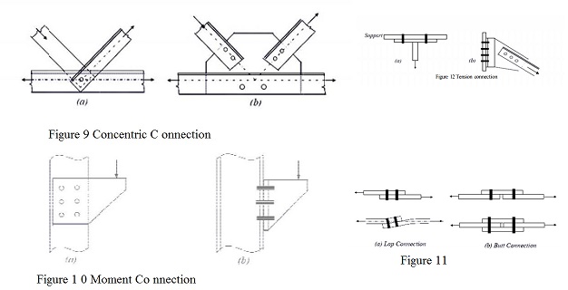
Ideal concentric
connections should have only one bolt passing through all the members meeting
at a joint as shown in Figure 9(a). However, in practice, this is not usually
possible and so it is only ensured that the centroidal axes of the members meet
at one point as shown in Figure 9(b).
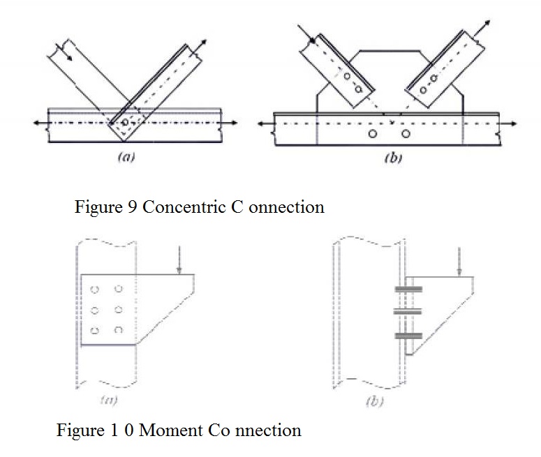
The Moment connections
are more complex to analyse compared to the above two types and are shown in
Figure 10(a) and Figure 10(b). The connection in Figure 10(a) is also known as
bracket connection and the resistance is only through shear in the bolts. The
connection shown in Figure 10(b) is often found in moment resisting frames
where the beam moment is transferred to the column. The connection is also used
at the base of the column where a base plate is connected to the foundation by means
o f anchor bol ts. In this co nnection, th e bolts are subjected a combinati on of shear and axial to tensi.
2. B ased on the type
of force
Bolt connections can be classified in to the following based on the type of force transferred:
(a) Shear connection - when the load transfer is through shear.
Eg. Lap joint and tension joint;
(b) Tension joints - when load
is transferred by
tension in the bolts. Eg.
Hanger connection;
(c) Combined shears and tension connections - when load is transferred
through the combinations of shear
and tension. Eg. Inclined members connected to columns or beams.
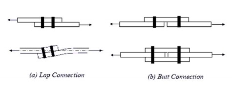
Typical shear connections occur as a lap or a butt joint used in the tension members as shown in Figure 11. While the lap joint has a
tendency to bend sothat the forces tend to become collinear, the butt joint
requires cover plates. Since the load acts in the plane of the plates, the load transmission at the joint will ultimately be through shearing forces in the bolts.
In the case of lap joint or a single cover
plate butt joint, there is only one
shearing plane, and so the bolts are said to be
in single shear. In the case of double
cover butt joint, there are two shearing planes and so the bolts will be
in double shear. It should be noted that
the single cover type butt joint is nothing but lap joints in
series and also bends so that the
centre of the cover plate becomes collinear with the forces. In the of single cover plate (lap) joint, the thickness of the cover plate is chosen to be equal to or
greater than the connected plates. While in double
cover plate (butt) joint, the
combined thickness of the cover plates should be equal to or greater than the connected plates.
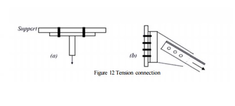
A hanger connection is
shown in Figure 12(a). In tension in the bolts. In the connection shown in
Figure and shear.
this connection, load
transmission is by pure 12(b), the bolts are subjected to both tension
3. On the basisof force
transfer mechanism
Bolt connections are
classified into the following based on
the way in which load is transferred from one member to another connected in the joint.
(a) Bearing type- bolts
bears against the holes to transfer the
load from one member to another. Eg. Slip type connection.
(b) Friction type - when the force is transferred by friction
between the plates due to tensioning of bolts.
Eg. Slip-critical connects.
Related Topics