Chapter: civil : Design Of Steel Structures
Analysis And Design Of Fillet Welds
Analysis And Design Of Fillet Welds
ASSUMPTIONS IN THE ANALYSIS OF WELDED JOINTS
The following assumptions are made in the analysis of welded
joints.
� Welds
connecting various parts are homogeneous, isotropic and elastic.
� The
parts connected by welds are rigid and their deformations are therefore
neglected.
�
Only stresses due to external loads are
to be considered. Effects of residual stresses, stress concentrations and shape of welds
are neglected.
ANALYSIS
AND DESIGN OF FILLET WELDS
Fillet welds are provided for
connecting two members which are overlapping each other. Shear stresses are
usually the type of stress in the case of fillet welded connection. Direct
stresses to which the connections are subjected to are usually of lesser
importance. Concave fillet weld was favoured because it offers a smoother path
for the flow of stress. But concave fillet weld up on cooling shrinks and cause
tension to the surface which may cause cracks in the joint. On the other hand,
shrinkage of weld will cause compression in the case of convex fillet weld.
Concave fillet welds are more suitable under alternating stresses.
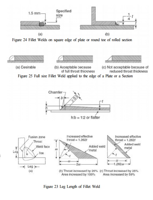
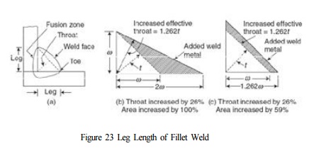
1. Size of Fillet weld
Cl.10.5.2.1 of IS800-2007 specifies the size of normal fillets
shall be taken as the minimum weld leg size. For deep penetration welds, where
the depth of penetration beyond the root run is a minimum of 2.4 mm, the size
of the fillet should be taken as the minimum leg size plus 2.4 mm. Figure 23
shows the leg length of fillet weld for various cases.
Cl.10.5.2.3 of IS800-2007
restricts minimum size of fillet welds to be 3 mm. The minimum size of the
first run or of a single run fillet weld shall be as given in Table 21 of IS800-2007,
to avoid the risk of cracking in the absence of preheating. Table 21 if
IS800-2007 is reproduced for ready reference as Table 6.
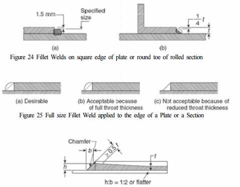
As per Cl.10.5.8.3 of IS800-2007,
where the size specified for a fillet weld is such that the parent metal will
not project beyond the weld, no melting of the outer cover or covers shall be
allowed to occur to such an extent as to reduce the throat thickness (see Fig.
18 of IS800:2007). The figure is reproduced here as Figure 25.
Cl.10.5.8.5 of IS800-2007
specifies for end fillet weld, normal to the direction of force shall be of
unequal size with a throat thickness not less than 0.5t, where t is the
thickness of the part, as shown
in Fig. 19 of IS800-2007. The
difference in thickness of the welds shall be negotiated at a uniform slope.
Fig. 19 of IS800-2007 is reproduced here as Figure 26.
Table 6
Minimum size of first run or of a single run fillet weld
SN Thickness of thicker part (mm)
Over Up
to and including - Minimum size (mm)
1 - 10 3
2 10 20 5
3 20 32 6
4 32 50 8
of 1st run, 10 for minimum weld size
Cl.10.5.8 of IS800-2007 specifies the maximum size of fillet
weld applied to the edge of a plate
or section. Cl.10.5.8.1 specifies
where a fillet weld is applied to the square edge; the specified size of the
weld should generally beat least 1.5 mm less than the edge thickness (see Fig.
17A of IS800:2007). This figure is reproduced here as Figure 24(a).
Cl.10.5.8.2 of IS800-2007 gives the specification where the
fillet weld is applied to the rounded toe of a rolled section; the specified
size of the weld should generally not exceed 3/4 of the thickness of the
section at the toe (see Fig. 17B of IS800:2007). This figure is reproduced here
as Figure 24(b).
2. Effective throat thickness of fillet welds
Cl.10.5.3 of IS800-2007 gives the specification for Effective
Throat Thickness. Cl.10.5.3.1 specifies the effective throat thickness of a
fillet weld not to be less than 3 mm and shall generally not exceed 0.7t, or
1.0t under special circumstances, where t is the thickness of the thinner plate
of elements being welded. Further, Cl.10.5.3.2 of the code specifies the
effective throat thickness. For the purpose of stress calculation in fillet
welds joining faces inclined to each other, the effective throat thickness
shall be taken as K times the fillet size, where K is a constant, depending
upon the angle between fusion faces, as given in Table 22 of IS800-2007. Table
22 of IS800-2007 is reproduced here as Table 7 for ready reference.
Table
7 Values of K for different angles
Angle between fusion faces in degrees 60-90
91-100 101-106 107-113
114-120
Constant, K 0.70 0.65 0.60 0.55 0.50
3. Effective length of fillet welds
Effective Length of Weld is
considered in accordance with Cl.10.5.4 of IS800-2007. As per Cl.10.5.4.1, the
effective length of fillet weld shall be taken as only that length which is of
the specified size and required throat thickness. In practice the actual length
of weld is made of the effective length shown in drawing plus two times the
weld size, but not less than four times the size of the weld. So the effective
length of the weld is considered as actual length minus twice the weld size. As
per Cl.10.5.1.1, Fillet welds terminating at the ends or sides of parts should
be returned continuously around the corners for a distance of not less than
twice the size of the weld, unless it is impractical to do so. This is
particularly important on the tension end of parts carrying bending loads.
4. Effective area of fillet welds
The effective area of fillet
welds is obtained as the product of effective throat thickness and effective
length.
5. Design strength of fillet welds
Cl.10.5.7.1.1 of IS800-200 deals with the strength
of fillet welds. As detailed in this clause of the code, fillet welds shall be
designed based on the throat area (effective area). The code specifies the
design stress in the weld fwd= fwn/rmw
where and fwm is partial safety factor
of the material of the weld given by Table 5 of IS800-2007 and is the nominal stress of the material given
by fwn=Tdw=Lwtt . lu/31/2.rmw
is the ultimate stress of the material. Hence the design capacity of fillet
welds effective length of the weld is and ??is
the throat thickness.
6. Long joints
When the length of the welded joint, lj of a splice
or end connection in a compression or tension element is greater than 150 tt
the design capacity of weld, fwd shall be reduced by the factor ???1
7. Fillet weld subjected to individual stresses
Cl.10.5.9 of IS800:2007 specifies
the Stresses Due to Individual Forces. When subjected to either compressive or
tensile or shear force alone, the stress in the weld is given by FU/(3rmv)1/2
8. Fillet
welds subjected to combination of stresses
![]()
![]()
As per Cl.10.5.10.1.1, when
subjected to a
combination of normal
and shear stress,
the
equivalent stress fe shall satisfy the condition fa
=(fa2 +3q2)1/2 <=FU/(3rmv)1/2
Related Topics