Chapter: civil : Design Of Steel Structures
Analysis And Design Of Butt(Groove) Welds
Analysis And Design Of Butt(Groove) Welds
ASSUMPTIONS IN THE ANALYSIS OF WELDED JOINTS
The following assumptions are made in the analysis of welded
joints.
�
Welds connecting various parts are
homogeneous, isotropic and elastic.
�
The parts connected by welds are rigid
and their deformations are therefore neglected.
�
Only stresses due to external loads are
to be considered. Effects of residual stresses, stress concentrations and shape of welds
are neglected.
ANALYSIS AND DESIGN OF BUTT(GROOVE) WELDS
Groove welds are usually provided when the member
is subjected to tension or compression. Since there is no change in the section
at the joint, this is the most suitable form of joint to transfer alternating
stress. However when the welds are intended to take shear stress, careful
consideration should also be made so that the shear stresses developed is taken
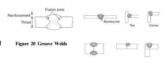
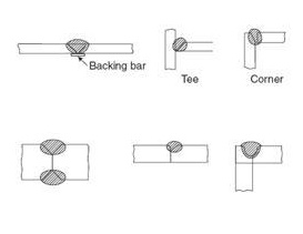
care of. Figure 20 shows the typical cross section of a groove weld. Square
groove welds are usually employed for sections of thickness up to 8mm. If sections
with more than 8mm thickness, U, V, double U or double V butt welds are used.
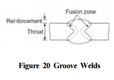
1. Reinforcement in Groove Welds
Extra weld material which is
deposited to make the throat thickness at least 10% more than the welded
material is known as reinforcement (see Figure 20). This will increase the
efficiency of the joint. Reinforcement will increase the strength of grove
welds under static loading. In the case of dynamic loading, reinforcement may
result in stress concentrations. So the reinforcement is usually dressed flush
in the case of members subjected to dynamic loading. However subsequent removal
of reinforcement is not considered as reducing the strength of joint. The
reinforcement is ignored in calculating the strength. In any case the
reinforcement should not exceed 3mm.
2. Size of Groove Welds
Size of welded joint is usually
specified by throat dimension. This is also called effective throat thickness.
Groove welds may be classified in to full penetration groove welds (Figure 21)
or partial penetration groove welds (Figure 22). Complete penetration is
difficult to achieve in the case of single U, V, J and bevel welds. However,
this can be achieved by using backing strips as shown in Figure 21.
As per Cl.10.5.3.3 of IS800-2007,
the effective throat thickness of a complete penetration butt weld shall be
taken as the thickness of the thinner part joined, and that of an incomplete
penetration butt weld shall be taken as the minimum thickness of the weld metal
common to the parts joined, excluding reinforcements. However in the case where
full penetration groove welds cannot be achieved, an effective throat thickness
of 1/8th of the thickness of thinner member is used. But for
calculating the strength of the connection, a throat thickness of 5/6th
of the thinner member is usually assumed.
3. Effective area of Groove Welds
Effective area of weld is obtained as the product of effective
length, ? of weld and effective
thickness (throat thickness), ??of weld. As per Cl.10.5.4.2 of IS800-2007, the
effective length of butt weld shall be taken as the length of the continuous
full size butt weld, but not less than four times the size of the weld.
4. Design strength of Groove welds
Cl.10.5.7.1.2 of IS800-200 deals
with the strength of Butt welds. As detailed in this clause of the code, Butt
welds shall be treated as parent metal with a thickness equal to the throat
thickness, and the stresses shall not exceed those permitted in the parent
metal. Hence the following equations may be used for the design of butt welds.
The design strength of groove
weld in tension and compression is given by
Tdw=Tnw/rmw where Tnu is the nominal strength of the weld given by
Tnw=fyLwtt and is partial safety factor of the material of the weld given by
Table 5 of IS800-2007. Fy is the yield stress of the material, Lw is the
effective length of the weld and Le is the throat thickness.
The design strength of groove
weld in shear may be calculated by the expression Tdw=Tnw/rmw where ? is
partial safety factor of the material of the weld given by Table 5 of IS800- ?is the
nominal strength of the weld given by ? ? where ? is the 2007
and ? ????? ? ?.
ultimate stress of the material, ?is the
effective length of the weld and ? is the throat thickness.
5. Butt welds subjected to
combination of stresses
Cl.10.5.10.2.2 deals with the
case where fillet welds are subjected to combined bearing, bending and shear.
Where bearing stress, fbr, is combined with bending (tensile or compressive),
fb and shear stresses, q under the most in
butt welds, the equivalent stress, fe, obtained from the formula fc = (fb2+fbr2+fbfbr+3q2)1/2. However the value of fe thus obtained shall
not exceed the values allowed for the parent metal:
Related Topics