Chapter: civil : Design Of Steel Structures : Introduction
Properties Of Structural Steel

PROPERTIES OF STRUCTURAL STEEL
The properties of structural steel, as per clause
2.2.4 of IS 800:2007, for use in design, may be taken as given in clauses
2.2.4.1 and 2.2.4.2 of the code.
1.
Physical properties
Physical properties of structural steel, as
detailed by cl.2.2.4.1 of IS 800:2007, irrespective of its grade may be taken
as: a) Unit mass of steel, p = 7850 kg/m3 b) Modulus of elasticity,
E = 2.0x10⁵ N/mm2 (MPa) c) Poisson ratio, p = 0.3 d)
Modulus of rigidity, G = 0.769x10⁵ N/mm2 (MPa) e)
Coefficient of thermal expansion cx.=12x10 -6/0C
2.
Mechanical properties
The
principal mechanical properties of the structural steel important in design, as
detailed by the code IS 800:2007 in cl. 2.2.4.2, are the yield stress, f y;
the tensile or ultimate stress, fu; the maximum percent elongation
on a standard gauge length and notch toughness. Except for notch toughness, the
other properties are determined by conducting tensile tests on samples cut from
the plates, sections, etc, in accordance with IS 1608. Commonly used properties
for the common steel products of different specifications are summarized in
Table 1 of IS 800:2007. Highlights of the table are reproduced for ready
reference as Table 1.

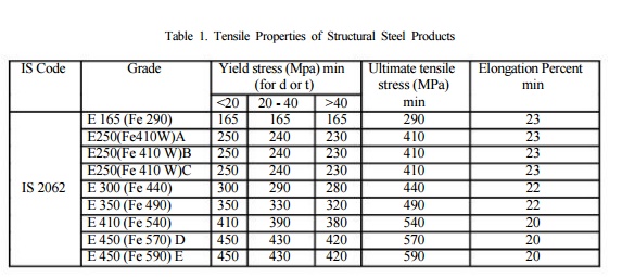
Table 1.
Tensile Properties of Structural Steel Products
IS Code Grade Yield stress (Mpa) min Ultimate tensile Elongation Percent
(for d or t) stress (MPa) min
<20 20 - 40 >40 min
E 165 (Fe 290) 165 165 165 290 23
E250(Fe410W)A 250 240 230 410 23
E250(Fe 410 W)B 250 240 230 410 23
E250(Fe 410 W)C 250 240 230 410 23
IS 2062
E 300 (Fe 440) 300 290 280 440 22
E 350 (Fe 490) 350 330 320 490 22
E 410 (Fe
540) 410 390 380 540 20
E 450 (Fe
570) D 450 430 420 570 20
E 450 (Fe
590) E 450 430 420 590 20
2.1.
Stress - strain behaviour: tensile test
The
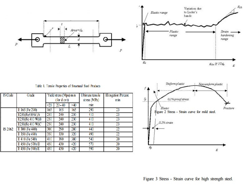
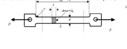
stress-strain curve for steel is generally obtained from tensile test on
standard specimens as
given in Figure 1. The details of the specimen and the method
of testing is elaborated in IS: 1608
(1995). The important
parameters are the gauge length 'Lc'
and the initial cross section area So. The
loads
are applied through the threaded or shouldered ends. The initial gauge length
is taken as 5.65?So in the
case of rectangular specimen and it is five times the diameter in the case of
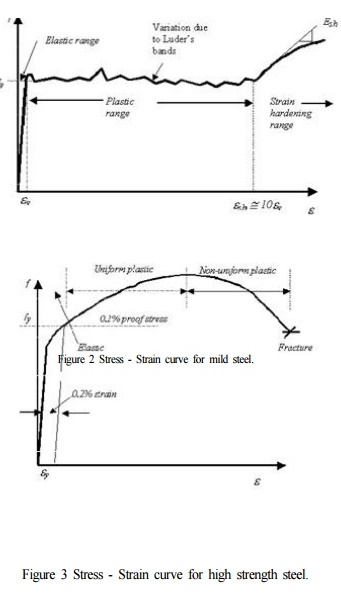
circular specimen. A typical stress-strain curve of the tensile test coupon is
shown in Figure 2 in which a sharp change in yield point followed by plastic
strain is observed. After a certain amount of the plastic deformation of the
material, due to reorientation of the crystal structure an increase in load is
observed with increase in strain. This range is called the strain hardening
range. After a little increase in load, the specimen eventually fractures.
After the failure it is seen that the fractured surface of the two pieces form
a cup
and cone arrangement. This cup and cone fracture is considered
to be an indication of ductile fracture.
It is seen from Figure 2 that the elastic strain is
up to ?y followed by a yield plateau between
strains ?y and ?sh
and a strain hardening range start at ?sh
and the specimen fail at ?ult where ?y,
?sh
and ?ult are the
strains at onset of yielding, strain hardening and failure
respectively.
Depending
on the steel used, ?sh generally varies
between 5 and 15 ?y, with an average value of 10
?y typically used in many applications. For all structural steels, the modulus of elasticity can be taken as 205,000 MPa and the tangent modus at the onset of strain hardening is roughly 1/30th of that value or approximately 6700 MPa. High strength steels, due to their specific microstructure, do not show a sharp yield point but rather they yield continuously as shown in Figure 2. For such steels the yield stress is always taken as the stress at which a line at 0.2% strain, parallel to the elastic portion, intercepts the stress strain curve.

The nominal stress or the engineering stress is given by the
load divided by the original area. Similarly, the engineering strain is taken
as the ratio of the change in length to original length.

2.2. Hardness
Hardness is regarded as the resistance of a material to
indentations and scratching. This is generally determined by forcing an
indentor on to the surface. The resultant deformation in steel is both elastic
and plastic. There are several methods using which the hardness of a metal
could be found out. They basically differ in the form of the indentor, which is
used on to the surface. Brinell hardness usually uses steel balls where as
Vickers hardness uses square based diamond pyramid with 1350 and
Rockwell hardness uses diamond cone with 1200 angle. In all the
above cases, hardness number is related to the ratio of the applied load to the
surface area of the indentation formed. The testing procedure involves forcing
the indentor on to the surface at a particular road. On removal, the size of indentation
is measured.
2.3. Notch Toughness
There is always a possibility of microscopic cracks in a
material or the material may develop such cracks as a result of several cycles
of loading. Such cracks may grow rapidly without detection and lead to sudden
collapse of the structure. To ensure that this does not happen, materials in
which the cracks grow slowly are preferred. Such steels are known as
notch-tough steels and the amount of energy they absorb is measured by
impacting a notched specimen with a heavy pendulum as in Izod or Charpy tests.
Related Topics